 Flexibility, adaptability and reliability: nowadays machine vision systems are standard discipline for the research and the development of new automation techniques at the service of a hostile environment like foundry.
Machine vision advantages in foundry
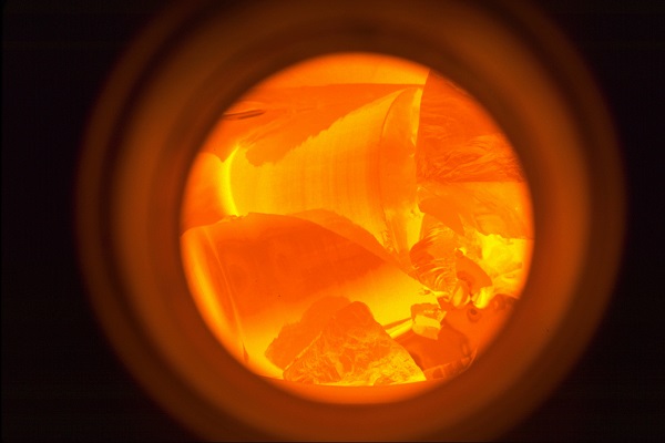
The shape control, the analysis and the testing of casting material components, the measuring of the fundamental processing parameters are among the most common applications of the machine vision. Besides, they are used as control systems of presences and accesses in the working areas close to machinery and in the zones in which particular measures for operators’ safety are requested. The image processing calls for different instruments, from a simple vision sensor to a smart camera, up to laser measuring systems.
Machine vision technologies
The availability of computerized instruments able to process complex calculation procedures allows the development of new vision functions, not only in the two x and y dimensions, but also in the third z dimension, making them accessible in a single graphic development environment.
The most common approaches of vision techniques include the three following categories: stereoscopic vision, structured light systems and vision sensors.
Stereoscopic vision
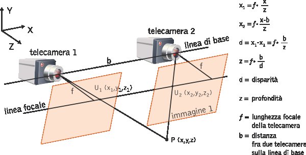
It is the modality that most resembles the functioning of the human brain to measure distances: the images captured by each eye are processed by the brain, the difference in the images due to the displacement between the two eyes is used to confer the perspective, fundamental to judge distances.
In practice, two cameras mounted with two perspectives of the same object are adopted, the information of the camera pixels are aligned through calibration and then the datum abut depth is drawn out (Figure 1).
Structured light systems
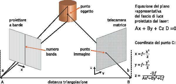
Structured light systems, called also full-field, use for their operation the projection of a regular pattern of known shape, generally consisting of vertical or parallel lines, on the object surface. The information about the depth is calculated by analysing the pattern distortion on the object surface.
That distortion induced by the object is acquired through a camera and exploited for the calculation of spatial coordinates (x,y,z). Depending on the camera resolution, a system of this type allows the digitizing not of a single point at a time but of hundred thousands of points. Besides, the geometry of the lit surface, or luminous section, can be reconstructed with high precision. The operation principle with which it is possible to reconstruct the shape of the hit object is based on the triangulation (Figure 2).
Laser measuring systems
The operation principle is based on the capability of emitting an electronic impulse and of receiving the reflected signal by measuring the time interval elapsed, that is to say the distance between the instrument and the detected point (x,y,z). For each measurement (x,y,z), the system provides the return signal intensity, describing the surface of the scanned object.
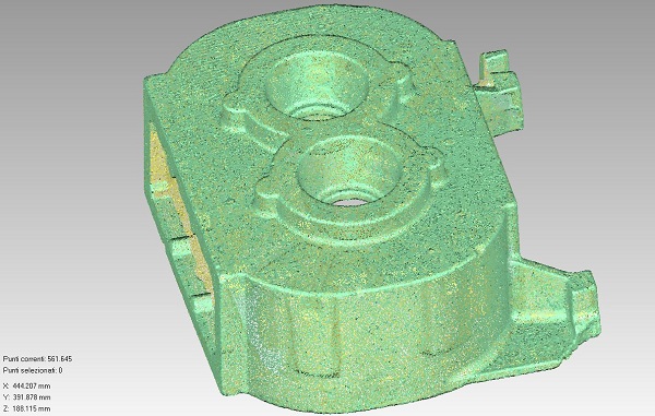
Such systems can detect even dozen thousands of points per second, providing what are called clouds of points (Figure 3), which need then the computer processing.
After the correct instrument positioning, the data acquisition produces the generation of the cloud of points of the scanned object.
From the project to the final product
The machine vision can find application during the whole process, both starting from the preliminary studies in design phase and during the casting, both in the final phase of qualitative and dimensional piece control.
Before the process: casting simulation
Casting analysis software are programmed in such a way as to simulate the process characteristics, both from the metallurgical point of view (chemical analysis, eutectic temperatures and so on) and from the point of view of the typology of materials used for the casting (moulding sands, cores, feeding sleeves), permitting to intervene preventively on the production making the process more efficient and cheaper.
Depending on the specific production requirements, they can be set to simulate, through generation of a mesh and finite difference calculation, the filling, solidification and cooling phases of the piece, assessing also the residual stresses and the possible formation of defects that would affect the cast part quality even before the casting process, like solid or gaseous inclusions, or also shrinkage cavities or other events of different nature.
Through the 3D simulation, it is possible to highlight such criticalities preventively: matrix areas subjected to higher thermal and mechanical stresses, filling time, analysis of liquid flows inside the matrix and correct directionality of the casting cooling, with study of the casting feeding system.
During the process: measuring the fundamental parameters
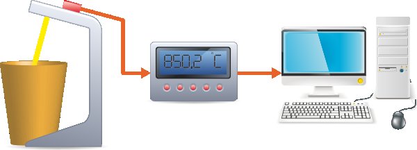
The temperature of the cast material and the level of the liquid metal are two essential parameters to test the correct execution of the casting process and to obtain a material with the desired mechanical characteristics from the casting.
Instead of immersion thermocouples, optical infrared pyrometers are already widely used for measuring very high temperatures. The technologies of the most recent infrared sensors with very short wavelength show more than satisfactory results in terms of precision, fast reading and use flexibility, maintaining at the same time the well- known sturdiness qualities.
Expressly designed for the casting industry, they can be also configured to monitor more casting points simultaneously, under safety conditions and without interrupting the production, reducing costs and improving the product quality.
Two-dimensional laser sensors are the perfect solution to carry out level controls of liquid metal in high-quality castings. This technology provides decisive advantages in comparison with traditional methods, for instance in view of the metal content measuring in continuous chill casting, also with materials like aluminium, copper and magnesium.
By measuring the distance and the difference, we can achieve results of great efficacy and characterized by high precision, irrespective of the vertical position tolerance and of the sensor assembly, with advanced image evaluation also through fumes and vapours. A laser beam vertically directed on the liquid metal contained in the chill reproduces, along the whole surface line, some reflections that, through a precise and tuned optical lens, are consequently sent to the two-dimensional matrix of the laser sensor.
Special filtering methods and algorithms of the image evaluation successively provide for a reliable definition of the measurement value. With a measuring setup, according to the same principle, occurs the definition of the distance that goes from the sensor to the reference point projected on the chill surface. The difference of the two distances (liquid metal and chill surface) provides then the output signal, which therefore visualizes, and still through the evaluation system, the continuous level of the liquid metal (Figure 5).
Final phase: dimensional assessment and testing
The dimensional control is an advantage exclusively offered by vision systems, not feasible with traditional photocell systems. The complex geometries, both inside and outside the casting, the axis distance between two holes or two critical points, the internal and external diameters are just some examples of verifications that can be performed with a precision that, in certain cases, can be inferior to 0.1 millimetres. Fig.6
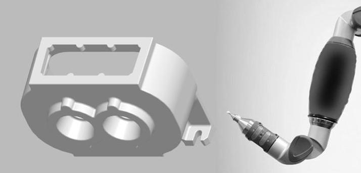
Automation and machine vision: a modern example in die casting
One of the most common configurations of artificial vision in die casting is formed by three parts: a suitable camera for the foundry environment, a sturdy personal computer connected with the electronic card that manages the camera and that is interfaced with the pulling out robot, a lighting system of the part, selected according to customers’ specific requirements and the environment where it is integrated.
The control of the cast part integrity when taken out is, in fact, one of the most common applications of the machine vision, which replaces the traditional photocell reflex on-off system, with numerous advantages. While the standard system compels the operator to the physical arrangement of the photocells in the points to be controlled whenever a die change is performed, the machine vision completely eliminates this function, since the image of the integer part, stored in the computer, is automatically recalled by the control system of the press. Besides, the machine vision allows checking the complex geometries both of external profiles and of through- and dead holes. Fundamental is the possibility of inspecting also other parts of the cast piece, like for instance wells or burrs in critical points, which are often the cause of undesired downtimes.
In addition to that, with the vision system it is possible to control the presence and the correct introduction of a metal insert into the casting process, reducing the possibility of producing rejects, especially when fully automated systems are involved.
Research activity carried out in the ambit of the intervention programme “From technological districts to industrial districts”, financed by Emilia Romagna Region.


