 The present article deals with milling operations. It explains how choices of tooling and cutting parameters affect the generation, absorption, and management of heat in the interrupted cutting conditions that characterise the milling process.
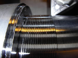
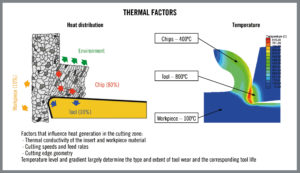
Metalcutting generates temperatures as high as 800 to 900 degrees Celsius in the zone where the cutting edge deforms the workpiece material and shears it away. In continuous turning operations, the heating occurs in a steady linear fashion. In contrast, the teeth of a milling cutter intermittently enter and exit the workpiece material and the temperature of the cutting edges alternately rises and falls.The elements of the machining system absorb the heat created in metalcutting. Typically 10 percent of the heat flows into the workpiece, 80 percent into the cut chips and 10 percent into the tool. It is best when the chips carry away most of the heat because high temperatures shorten tool life and can damage the part being machined.
 Thermal factor
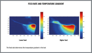
The differing thermal conductivity of workpiece materials, as well as other operational factors, has significant influence on the distribution of heat. For example, the thermal conductivity of superalloys is poor. When machining workpieces with poor conductivity, an increased amount of heat transfers into the tool. Further, harder materials produce more heat than softer materials when machined. And, in general, higher cutting speeds increase the production of heat while higher feed rates broaden the area of the cutting edge that is subject to higher temperatures.
Arc of engagement
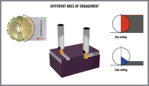
Due to the intermittent nature of the milling process, the cutting teeth are generating heat for only a portion of the total machining time. The percentage of time the teeth are cutting is determined by the milling cutter’s
arc of engagement, which is influenced by the radial cutting depth and the cutter diameter.
The various milling processes have differing arcs of engagement. In slot milling, for instance, the workpiece material surrounds half of the cutter during machining; the arc of engagement is 100 percent of the tool diameter. The cutting edges spend half the machining time engaged in the cut and heat builds up rapidly. That situation is distinct from side milling, in which a relatively small percentage of the cutter is engaged in the workpiece at any one time and the cutting edges have a greater chance to dissipate heat to the air.
Excessive heat buildup in the tool degrades tool life by causing accelerated wear or deformation.
Conversely, many cutting tool materials must be applied at temperatures above a critical minimum level to achieve full efficiency.
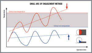
Carbide cutting tools, particularly, are composed of powder metal that is hard but brittle. Temperatures higher than a certain minimum level increase the toughness of powder metal materials and reduce their tendency to fracture. In contrast, when cutting temperatures are too low, the tool remains brittle and the result is breakage, chipping or edge buildup.The goal is to maintain an ideal zone of cutting temperatures.
Chip thickness and thermal issues
The radial depth of cut, the cutting edge angle, the feed rate and chip thickness in addition of cutting speed influence the thermal loads of milling. Chip thickness affects thermal conditions and tool life at both extremes. If chips are too thick, the resulting heavy loads can generate excessive heat and chip or break the cutting edges. When chips are too thin, cutting takes place on a smaller portion of the cutting edge and increased friction and heat result in rapid wear.
The chips produced in milling continually change in thickness as the cutting edge enters and exits the workpiece. Consequently, tooling suppliers utilise the concept of “average chip thickness” to calculate cutter feed rates that will maintain the most productive thicknesses. Determining the correct feed rate involves factors including the cutter’s arc of engagement or radial depth of cut and the cutting edge angle of the cutting edges. The greater the arc of engagement, the lower the feed rate required to generate the desired average chip thickness. Similarly, with lesser cutter engagement the feed rate must be higher to achieve the same chip thickness. The cutting edge angle of the cutter also affects feed requirements. Maximum chip thickness occurs with a cutting edge angle of 90 degrees, so lesser cutting edge angles require a higher feed rate to achieve the same average chip thickness.
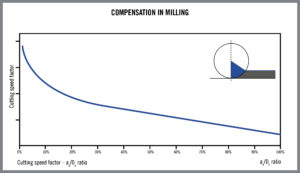
To keep the chip thickness and temperatures in the cutting zone at the same value as those for a fully engaged cutter, tool suppliers have developed compensation factors that call for increasing cutting speeds as the percentage of cutter engagement shrinks.
As an illustration, if the speed factor for a fully engaged (100 percent of diameter in cut) cutter is 1.0, the speed compensation factor for a 90-degree cutting edge angle cutter with 20 percent of its diameter engaged in the cut is 1.35. Therefore, if the cutting speed for the fully engaged cutter is 100 m/min, the cutting speed needed to maintain optimal chip thickness for the cutter with only a fifth of its diameter in the cut is 135 m/m.
From a thermal load point of view, if the arc of engagement is small, the time in cut may not be sufficient to generate the minimum temperature needed to maximise tool life. Because increasing cutting speed generally results in greater heat generation, combining low arc of engagement with higher cutting speed can help raise the cutting temperature to the preferred level. Higher cutting speed also reduces the amount of time the cutting edge is in contact with the chip, which in turn reduces the amount of heat that is transferred into the tool. Overall, higher speeds also reduce machining time and increase productivity. On the other hand, lower cutting speeds reduce machining temperatures. If the heat generated in an operation is too high, reducing cutting speed can lower the temperatures to an acceptable level.
Cutting edge geometry
The geometries of the milling cutter and its teeth contribute to the management of thermal loads. The basic geometry of the cutter determines how the tool is positioned relative to the workpiece. Cutters that position cutting edges at a positive rake (with the top of the cutting tooth sloping back from the workpiece material) produce lower cutting forces and generate less heat while also permitting use of higher cutting speeds.
However, a positive rake tool is weaker than a negative tool, and the hardness of the workpiece material and its surface condition may dictate use of negative rake cutters. Negative rake tools generate greater cutting forces and higher cutting temperatures.
The geometry of the cutting edges themselves initiate and control the cutting action and cutting forces, and thereby affect the generation of heat. The edge of the tool where it meets the workpiece can be chamfered, rounded or sharp. Chamfered or rounded edges are stronger, but once again produce higher cutting forces and more heat. A sharp edge, while not quite as strong, reduces cutting forces and runs cooler.
The T-land behind the cutting edge directs the chip and can be positive or negative, with the same tradeoff of lower operating temperatures for the positive design against the stronger but higher-heat-generating negative arrangement.
Because the cutting action in milling is interrupted, chip control features of milling tools generally are not as important as they are in turning. However, depending on the workpiece material and arc of engagement involved, the energy involved in forming and directing the chip can be significant. Tight or hard-breaking chip control geometries immediately curl the chip and generate higher cutting forces and heat. More open chip control geometries produce lower cutting forces and operating temperatures, but may not be appropriate for use with some combinations of workpiece material and cutting parameters.
Cooling questions
Manipulating coolant application is another way to manage temperatures generated in metalcutting operations. Excessive temperatures cause a cutting edge to wear rapidly or deform, so heat must be controlled as quickly as possible. To lower temperatures efficiently, cooling has to be directed to the source of the heat. However, it is extremely difficult, if not impossible, to inject coolant into the high-temperature cutting zone where pressure
between the chip and cutting edge is in the neighbourhood of 20,000 bar. In addition, coolant evaporates instantly in such a severe environment. Coolant may not be fully effective in removing heat in such a situation, but it may help to some extent. Exactly how much difference a stream of coolant makes is unclear; coolant effectiveness is a subject on its own. It is like a religion; you believe in it or you don’t. In general, if excessive heat is anticipated, coolant can be applied. In slot milling, for example, coolant use generally will not be harmful. It can help but how much is a subject for discussion. In side milling, however, where cutting temperatures can remain low, it is probably best not to apply coolant.
Conclusion
The multiple factors that together create the loads present in metalcutting operations do not operate separately. They influence each other throughout the machining operations. This article has discussed thermal issues in milling operations and how they relate to mechanical factors. Familiarity with the individual elements that comprise metalcutting loads as well as the overall results of their interaction will help manufacturers optimise their machining processes and maximise productivity and profitability.
The benefits of compensation
Calculated compensation factors for milling operations prescribe ways to vary cutting parameters in relation to cutter engagement and thereby maintain desirable process temperatures. Temperatures that are too low do not allow tool material to operate at maximum toughness and built-up edges may form, conditions that lead to broken or chipped cutting edges. Excessively high temperatures produce rapid edge wear or tool deformation. Compensating by way of parameter adjustments balances thermal and mechanical loads to optimise tool life and productivity.
Application of compensation factors also facilitates application of advanced milling strategies. For example, when utilising high speed machining (HSM) methods that employ small radial and axial cutting depths of cut, tool supplier application guides recommend increased cutting speeds. Without the higher, heat-generating speeds, the light cutting edge engagement of HSM may not produce temperatures high enough for optimal tool performance. Taken together, cutting parameters adjusted for HSM increase metal removal rates significantly.
Cutting tools selected for HSM applications should feature sharp cutting edges and be composed of hard cutting materials that exhibit good wear resistance. Efficient chip evacuation is crucial, especially for softer materials such as aluminium; tools with large chip gullets or open flutes are recommended. It is important that machine tools used for HSM should be able to operate at speeds high enough to meet the compensation specifications.
Hard milling strategies also benefit from parameter adjustments that balance thermal and mechanical loads. Because hard milling generates a large amount of heat, reducing depth of cut may be recommended. Providing the depth of cut and feed remain small, cutting speed can be used as a way to optimise cutting data.
Machine tools employed in hard milling must exhibit rigidity and vibration-damping capability sufficient to permit accurate machining under large cutting loads. Rigid toolholding systems provide further strength and resistance to vibration, and long extensions should be avoided if possible. Short, multi-flute cutting tools also contribute to process stability. Negative rake geometries and radial edge grinds strengthen cutting edges. High feed milling (HFM) strategies feature high feed per cutting tooth balanced by small depths of cut and moderate cutting speeds. The method provides high metal removal rates with cutting forces and power consumption lower than other strategies. Bending loads on the tool are lower, reducing the risk of vibration and enabling the use of longer, less rigid tools. Once more, the strategy is best employed on a rigid machine tool with sufficient speed and power. Tool lead angles should be selected to direct cutting force axially into the machine spindle.
In High performance machining (HPM), axial and radial depths of cut are maximised first, with feeds and cutting speeds then chosen to minimise tool wear. The method achieves high metal removal rates at the lowest cost. HPM requires specifically designed chip formers, strengthened cutting edges, and flutes that efficiently evacuate chips. HPM is well suited to removal of large volumes of material and the machining of difficult-to-cut materials.
Simple adjustments of cutting speed or other parameters will help control chip thickness and thereby thermal loads in straightforward milling operations. However, it is difficult to manipulate parameters to match the changing cutting conditions present when milling complex contours. For maximum productivity, advanced CAM software, combined with powerful CNC technology possessing look-ahead capabilities that can rapidly process large blocks of commands, permits application of advanced milling strategies including trochoidal toolpaths and corner peeling methods.


