In a metal cutting operation a tool deforms the workpiece material until it shears of in the form of chips. The deformation process requires significant energy, and the tool endures a variety of mechanical, thermal, chemical, and tribological loads. These loads eventually cause the tool to deteriorate and wear out or fail. Therefore, the goal for having a good metal cutting application is to balance the energy required to remove metal with the tool’s ability to reliably withstand the loads placed on it.
Understanding and manipulating correctly cutting parameters, tool geometries, tool materials, and other factors enable machinists to achieve a productive and cost-effective metal cutting process. Mechanical loads in turning operations are steady, while in milling they are dynamic, changing continually from small to large and back again. This analysis will concentrate on parameters and tool geometries in turning operations while a later discussion will examine the different issues that arise in milling.
Machining loads
The loads that act on a cutting tool fit in four basic categories: mechanical, thermal, chemical, and tribological.
Mechanical pressure accelerates tool wear and failure. Interrupted cuts encountered when machining parts having voids or inclusions produce impact loads that can cause a tool to chip or break. Thermal loads occur because deformation of the 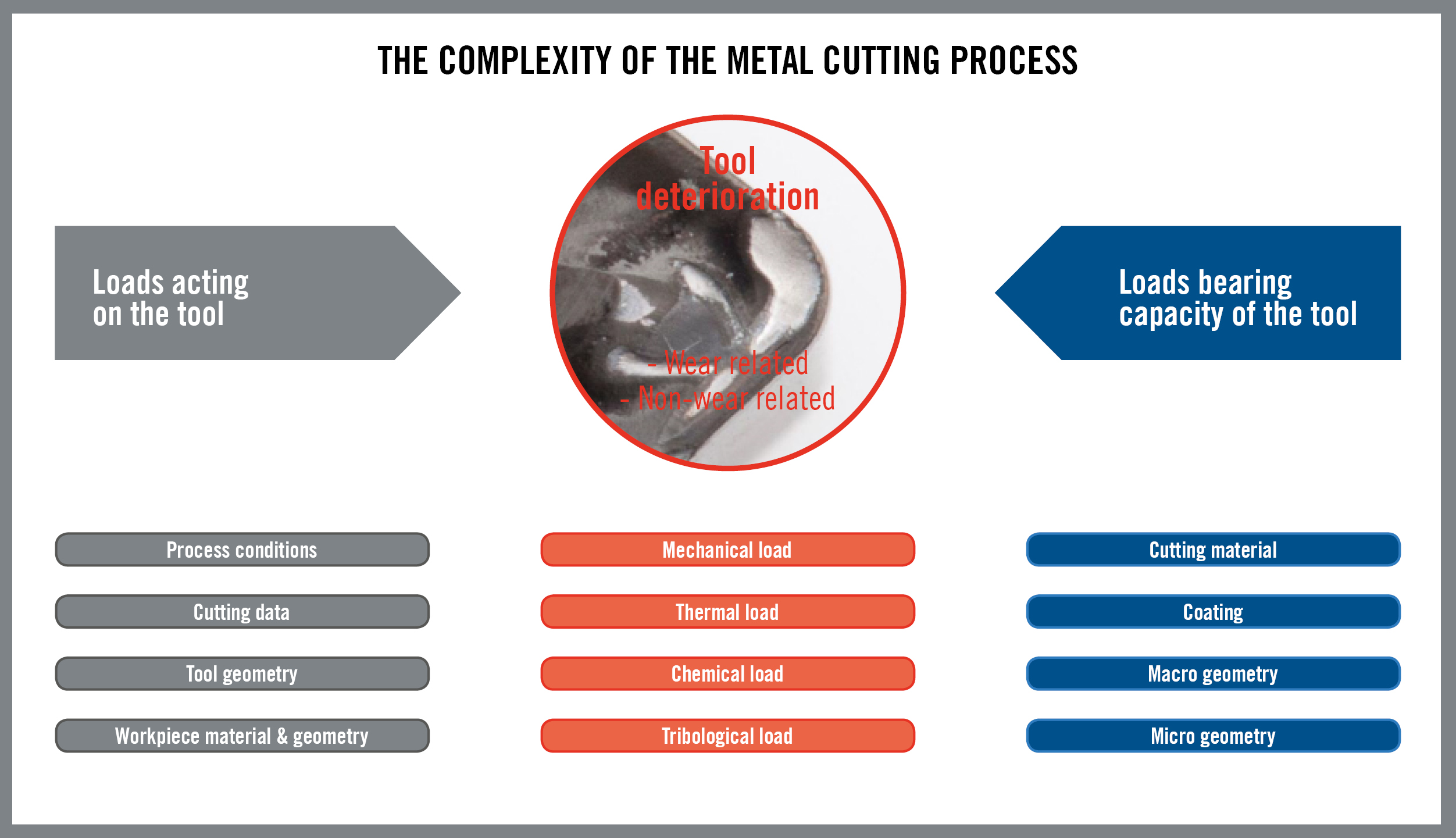 workpiece material generates heat which leads to increased temperatures in the range of 800-900 degrees Celsius, which can cause tool deformation and blunting.
The combination of heat and pressure also promotes chemical reactions between the cutting material and the workpiece material, producing wear in the form of diffusion or cratering. Friction between the tool and the chip generates abrasion and erosion wear, a result of what are called tribological loads; tribology being the examination of surfaces in contact with each other to determine how they will modify each other geometrically at certain temperatures and pressures.
The four categories of load do not operate independently but rather interact and influence the sum of their effects. The machine power involved, the rigidity of the machine and part fixturing, and even the skill of the machine operator also affect machining results. Interplay of the loads produces a variety of results, all with the same end: the tool deteriorates and wears out or fails.
How soon and predictably the end of the tool life occurs depends on the tool’s ability to withstand the loads to which it is subjected. For maximum tool life and process security, machining loads must be lower over a certain amount of time than the tool’s load-bearing capacity. Key contributors to that capacity include the tool’s cutting geometry and cutting material and coating.
Proactive problem solving
Seeking efficiency and cost savings, machine shops strive to reduce the time spent on machine setup, tool handling and workpiece handling, as well as other various idle times. Rarely, however, is problem-solving time included in the idle time reduction effort. Proactive application of appropriate tool geometries and cutting parameters before machining begins can reduce the time spent diagnosing and solving problems.
Machinability
Proactive planning aims at maximising the machinability of an operation. The traditional definition of machinability focuses on a particular workpiece material and employs percentage factors to measure how difficult the material is to machine compared to a benchmark material. In this discussion, however, machinability is defined as a target to achieve in terms of increasing metal removal rate per unit power. It is the degree to which a metal cutting operation can be executed in a reliable way, at highest productivity and lowest cost. 
The simplified approach to machining faster involves increasing cutting conditions, namely depth of cut, feed, and cutting speed. However, increasing cutting conditions has a number of consequences in regard to the loads placed on the cutting tool. In this analysis we concentrate on the mechanical loads. It should be understood that mechanical loads on the cutting tool and cutting force are not the same thing. Mechanical load can be thought of in terms of pressure (force per unit surface area). A high cutting force spread over a large area produces a relatively small load on the tool. On the other hand, even a low cutting force concentrated in a very small part of a tool can produce a problematic load. The cutting force is influenced by the workpiece material, tool geometry, and cutting conditions. In turn, the cutting force influences power consumption, vibration, workpiece tolerances, and tool life.
Effects odf cutting parameters
Manipulation of depth of cut, feed, and speed has differing effects in regard to load on the tool. Doubling the depth of cut doubles the cutting force but also doubles the length of the cutting edge in cut, so the load remains the same per unit of cutting edge length. Cutting forces also increase with increasing feed rate, but to a lesser, non-linear degree. Higher feed rates do not increase cutting forces to the same extent as larger depths of cut because the greater feed increases chip thickness, not the length of the tool in the cut. This leads to seriously increased loads on the cutting edge.
When increasing cutting speed, forces generally remain the same but power requirements rise, per the basic mechanical formula stating that power consumption equals force times velocity. It is true that over a middle range of cutting speeds forces are consistent. However, research and practical experience show cutting forces rising at lower cutting speeds and decreasing at higher cutting speeds. Increase of cutting force at low speeds may result from the appearance of a built-up edge, itself an indicator of inappropriate cutting speed. Research during the 1920s and 1930s by Dr. Carl Salomon of the University of Berlin determined that cutting temperatures increase with increasing cutting speed and then decrease as speed goes higher. These results move into the realm of truly high-speed machining, which has its own catalogue of causes and effects and is a topic for another discussion. 
Cutting speeds that are too high can reduce the reliability of a process through uncontrolled chip formation, extreme tool wear, and vibration that can make a tool chip or fracture. The practical conclusion is that higher feeds and depths of cut combined with low or moderate cutting speeds offer the best potential for operational security and reliability. Higher cutting speeds, if depth of cut and feed are sufficiently low to limit cutting forces, can provide greater productivity.
Problem solving via tool geometry
It is widely believed that increasing metal cutting productivity and solving problems requires introduction of more advanced cutting tool materials such as new carbide grades, coatings, ceramics and PCBN. The value of ongoing advances in tool material technology is undeniable. Nevertheless, solving problems with new cutting materials alone is essentially reactive and may lead to a dead end. For example, if heavy mechanical loads are causing problems such as tool breakage, the solution is to select a tougher cutting tool material. But if a tougher material does not exist, progress stops.The role of tool geometries in proactive problem solving is underappreciated. Changing tool geometries changes the flow of deformed material in an active way. For example, if the formula for predicting cutting forces (see sidebar) indicates that resulting mechanical loads will be high, starting with a sharper geometry can lower cutting forces and minimise a problem before it occurs. Modifying chip flow with a different tool geometry also can positively change the amount and effect of chemical, thermal, and tribological loads.
Elements of tool geometry
A tool’s geometry includes its shape and dimensions on both macro and micro levels. On the macro side, the basic size and shape of a cutting insert determines its strength. Cutting forces acting on a large insert will result in lighter loads than the same forces would create on a smaller insert. A large, strong insert enables use of highly productive feeds and depths of cut. However, a large insert may not be able to machine smaller part features. Similar considerations exist in regard to insert shape. A round insert shape is the strongest, and a 90-degree corner of a square insert is stronger than a 35-degree corner of a diamond insert. However, a round insert cannot cut the same variety of part profiles as a 35-degree tool. There is a tradeoff of strength for flexibility of application. Another geometric factor involves how the tool enters the workpiece, defined by the cutting edge angle, the inclination angle and the rake angle. If the insert top (rake) face is perpendicular to the work surface, the tool’s rake angle is considered to be negative. Cutting forces are directed into the bulk or strongest part of the tool. On the other hand, when the cutting edge is tilted back from the workpiece surface, the tool’s rake angle is considered to be positive. Cutting forces are concentrated on the tool edge, which is not as strong as the bulk. In addition, an insert applied in positive rake must feature a wedge or clearance angle on the flank face, further reducing tool strength.Negative rake machining is effective in tough materials such as steels and cast irons, but also produces higher cutting forces, may restrict chip flow, and may cause vibration in less-than-rigid machines, fixtures, or workpieces. Positive rake produces lower cutting forces and freer chip flow, but the tool is more susceptible to chipping and fracture, and chips may be uncontrolled. Positive cutting is suited for gummy materials and superalloys that require a sharp cutting edge.
Chipbraking geometry
The turning insert chipbreaking geometry has three basic components: the cutting edge profile, the chip control contour or groove, and the so-called T-land between the edge and the chip groove. The cutting edge profile begins the shearing process for the chip; the chip groove determines how the chip is formed; and the T-land manages the transition between the two. All three components influence the amount of cutting force the tool generates. The cutting edge can be sharp, honed, rounded, or chamfered. Each different profile provides specific benefits and produces specific consequences. In some cases, a sharp cutting edge can provide long tool life. However, the workpiece, machine tool, and fixturing must be solid and stable or the sharp edge will tend to chip when it is subjected to uneven forces. Rounded and chamfered edges provide increasing levels of strength and resistance to chipping and breakage.
In an extremely general sense, the best tool for cutting steel, where toughness is required, has a strong edge; the best tool for cutting stainless steel, which tends to be gummy, has a sharp edge. It is, of course, possible to cut steel with a sharp edge, or stainless with a strong edge, but the cutting conditions will have to be adjusted and the results will not be as productive. Machinists may face a choice between more flexible multi-purpose tools and those optimised for certain workpiece material applications. It is notable that a very sharp cutting edge may not necessarily provide the best surface finish. The best results often are obtained after an edge has run for a period of time. The phenomenon is analogous to using a razor-sharp knife to peel an apple. It is difficult to peel an apple with the sharpest of knives because the blade digs into the fruit instead of simply lifting away the skin. An absolutely sharp metal cutting tool will act very much the same way and be pulled into the workpiece to the degree that it leaves an uneven finish. The edge will provide the most consistent finish after it has experienced a small degree of wear.
The T-land between the cutting edge and the chipbreaking geometry can be positive or negative in configuration. Use of a positive T-land can enable use of higher cutting speeds and result in reduced cutting temperatures and wear. However, a positive T-land also concentrates stresses in a smaller area of the insert, which can lead to accelerated wear and chipping. A negative or basically flat T-land, conversely, channels the cut material across a wider area, protecting the insert, but also increasing cutting forces, heat generation, and wear.
The geometry of the chipbreaking groove presents a similar dichotomy. An open or flat bottom contour deforms the chip less and generates lower cutting forces. A closed or tighter contour curls the chip more acutely, and greater deformation generates higher cutting temperatures. An open or flat bottom chipbreaking geometry is engineered to maximise contact between the chips and tool and spread cutting forces over a wider region. When cutting forces are high, an open geometry will produce lower mechanical loads. Risks of insert breakage and chipping are lower. However, the chips produced by an open geometry tend to be longer. If chips are uncontrolled and become a disposal problem, posing a danger to the workpiece, machine, or operator, a closed chip breaking geometry may solve the problem.
On the other hand, a closed chip breaking geometry curls chips so they break into smaller pieces. But that result is achieved at the price of higher cutting pressures. Chips that are too short may damage the cutting edge and reduce tool life. The mechanical load can be heavy even when cutting forces are low. Closed geometries are best applied where cutting forces are light, as in finishing operations where depths of cuts and feeds are smaller. Machinists need to find a compromise and determine the widest geometry that can be applied while still generating controllable chips. The material being machined plays a key role in the choice of chip control geometry. Aluminium, for example, may require a closed chip control geometry to reliably break its characteristically long and stringy chips, while the short chips from cast iron generally require minimal if any chip-forming geometric features. 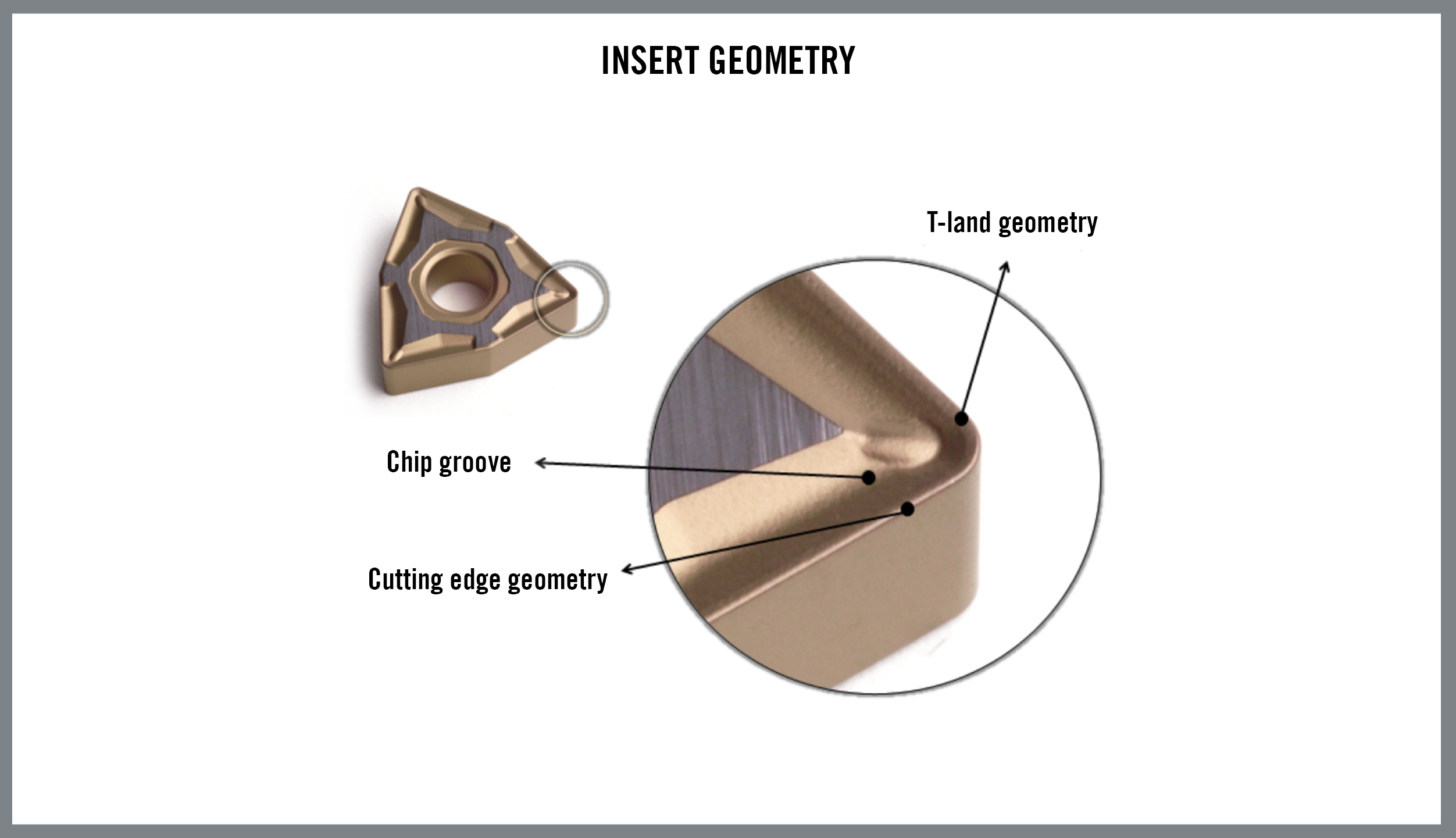
In regard to cutting parameters, a more aggressive feed will generally produce shorter chips, and small depths of cut will often result in longer chips. Depending on the workpiece material, cutting speeds can have a major influence on chip control. The goal is to control all the contributors to mechanical load and produce acceptable chips while minimising or eliminating tool chipping or breakage.
Geometry development and application
To take advantage of the ability of insert geometries to reshape the flow of material, cutting tool manufacturers develop geometries for specific operations such as roughing or finishing. Different configurations and combinations of cutting edge, T-land, and chip breaking geometries are engineered for different applications and workpiece materials. Seco’s M3 and M5 geometries are good examples of different tool geometries designed to achieve desired results in certain operations and materials. The M3 geometry is engineered to be a versatile tool for medium-rough machining for a wide range of 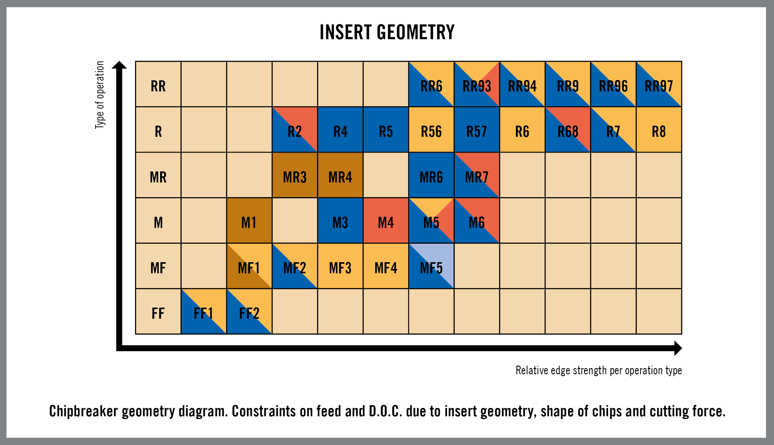 workpiece materials and cutting parameters. However, a high level of mechanical load may require a switch to an M5 geometry that is designed to handle demanding roughing operations at high feed rates, combining high end strength but generating low cutting forces. Moving to a geometry aimed at a specific machining situation can minimise breakage and boost operational reliability.
Conclusion
Tool deterioration during machining is inevitable. It is the alpha and omega, the beginning and the end, of tool life. If tool life is unacceptably short, if the tool chips or breaks, or if wear or failure is unpredictable, machinists can manipulate tool geometries and cutting conditions to maximise productivity and tool life. Even when those efforts are successful, however, the alpha and omega of tool deterioration remain. The goal is to establish a new mode of deterioration: one that is slow and predictable as possible.
Cutting force prediction
The interaction and balance of cutting parameters can be modeled with a cutting force formula developed in the 1950s by Dr. Otto Kienzle of the Institute of Production Engineering and Machine Tools (IFW) in Germany. Machinists can use the 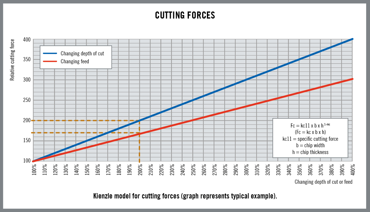 formula’s prediction of the level of cutting forces to proactively apply geometries and other factors and control loads on the cutting tool. The formula employs a material-based constant kc11 that is the specific cutting force (measured in N/mm2) needed to cut a chip area of 1 mm2 with a thickness of 1 mm in a specific material. In the formula, Fc =kc11*b*h 1-MC, the cutting force (Fc) is equal to the kc11 constant multiplied by “b” (the chip width/depth of cut), times “h” (the chip thickness/feed) and a power factor exponent 1-mc that takes into account the combination of geometry of the cutting tool and the workpiece material.


Good One….