What are the available instruments to assess the presence of residual stresses in castings and how can we determine their intensity? The term residual stresses means: “all those stresses contained inside a body when the latter is in conditions of balance with the surrounding environment”, and therefore without having any external evidence, to the extent that they are defined also as “internal stresses”.
“Internal” or “residual”, no matter how we define them, in a metal material such stresses always derive from some inhomogeneity conditions inside the material, inhomogeneity that in castings is generally coupled with the fact that the casting cooling does not occur simultaneously in all points, since the inner surface cools faster than the material core, and the zones with subtle walls before the more massive parts.
In general terms “the residual stresses are generated inside the component when inhomogeneity elements are present in the metallurgical or material process characteristics”.
In the case of castings, apart from macroscopic errors leading to have homogeneity differences of the material among the various zones of the part, the main source of residual stresses is undoubtedly the cooling process or, better, the non-simultaneous cooling among the various zones of the same component.

Reminding in fact that the specific volume of a metal material is directly proportional to temperature, it results that when the cooling of the external casting part occurs, the internal part is constituted by high-temperature material. When the cooling extends to the material core, too, this will not shrink freely because constrained by the external solidified surface: therefore, we will have the external part stressed by compression by the core material, which in its turn will be stressed by traction by the external part.
Analogue considerations are valid if the casting features parts with different thickness, with parts with subtle stabilized walls before the parts with bigger section, and then the establishing of mutual traction or even of deformations.
We can therefore state that the stress state in a casting with subtle walls has at least two components, one that we may define “vertical” induced by the interactions between the material on the surface and the underlying material, and a “geometrical” one induced by the constraints constituted by the surrounding material.
How much, anyway, do residual stresses influence defects in castings?
Much, I daresay very much.
We should just consider that in the international classification of casting defects, as standardized by ICFTA – International Committee of Foundry Technical Associations), 7 macro categories are provided, which we remind here as follows:
• Bumps
• Cavities
• Discontinuities
• Surface imperfections
• Incomplete casting
• Dimensional error
• Inclusions or structural anomalies
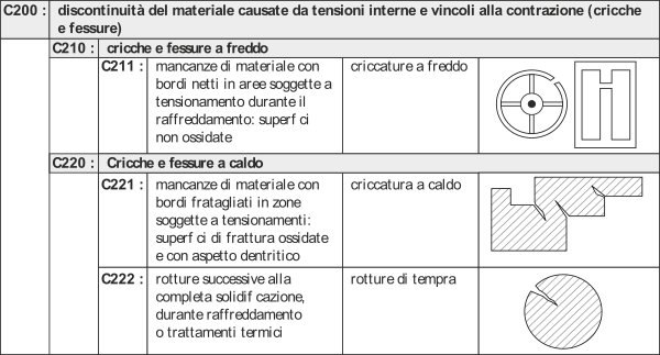
Inside discontinuity defects (C category), that is to say breakages detected at the extraction from the die, it is expressly provided the C200 sub-category “Discontinuities caused by internal tension and restraints to contraction (cracks and tears)”
Whereas in dimensional error defects (category F) there are a good 4 non-conformity typologies ascribable to residual stresses.
As we have often repeated, however, ,- the main danger of residual stresses is not that they lead to the breakage or deformation of the component at the extraction from the die but instead that they remain “hidden” inside the component, drastically decreasing the resistance in operation – : for this reason, then, it becomes essential the capability of measuring residual stresses in castings, at first as process setup instrument and afterwards as tool of product quality control.
THE MEASUREMENT OF RESIDUAL STRESSES: CUTTING, RING CORE AND HOLE DRILL
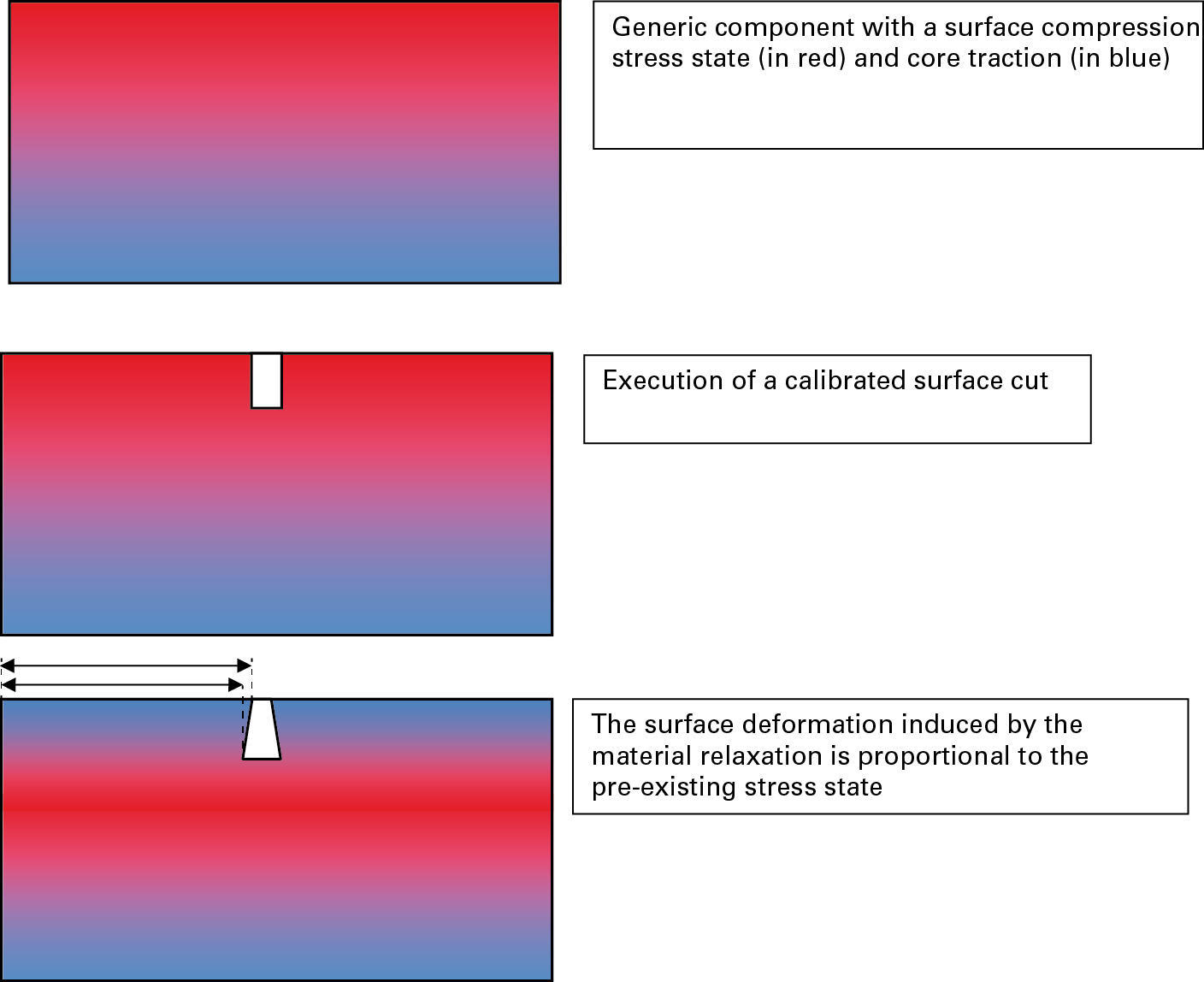
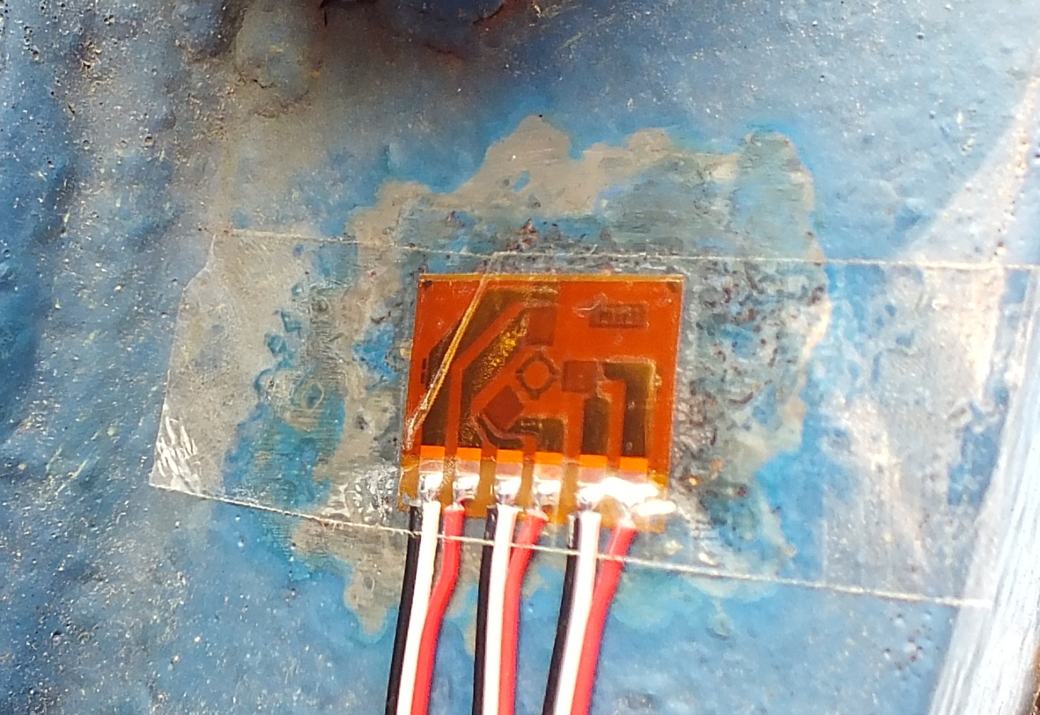
Essentially, the measurement of the residual stresses contained in castings occurs by exploiting the measurement by means of strain gages, from the component deformation, following the removal of a controlled quantity of material (according to the principle illustrated in figure 3) or as consequence of the breakage on an internal constraint.
The execution modalities of such operations make the measurement more or less destructive for the component: the most destructive methodologies are generally used for the qualification and the development of processes while less invasive methodologies are used for the quality control of castings anyway intended for use. In terms of component “destructivity”, we will speak then of cutting, ring-core and hole-drill.
In the application of the cutting technique, the method provides for the application of the strain gage on the zone to be investigated and for the “separation” of that zone from the adjacent material by means of a series of cuts (hence the method denomination).
Depending on the positioning of cuts, it is possible to separate the induced stress status, for instance by surrounding constraints, from that transmitted “on the surface” by more internal stresses. This method is clearly affected by the fact of being fully destructive for the analysed component but it offers the advantage of being easily applied and interpreted (considering that the released deformation corresponds to the entire present stress status, the pre-existing stress can be immediately deducted from the elastic constant of the material), as well as of permitting to separate the internal contribution of the material from that of surrounding constraints.

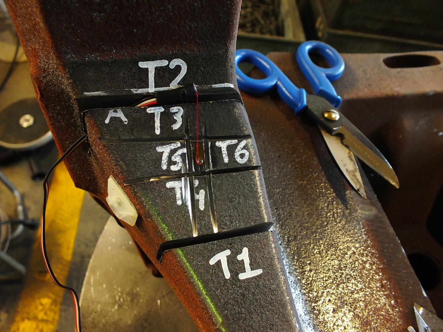
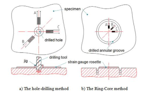
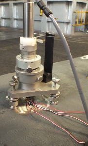
In the case of ring-core and hole-drill techniques, on the contrary, the stock removal is much more controlled and much smaller in quantity (even minimal in the case of the hole drill). In simple words, we can affirm that in the ring-core technique, the material is removed around the strain gage, which once more directly measures the complete material relaxation, while in the hole-drill technique the removed material is reduced to a very small hole of 2mm of depth and 1.6mm of diameter, and the deformation is measured radially outside that hole (see figure 7). In this case the material relaxation is only partial and the reconstruction of the overall stress is accomplished by an integral calculation algorithm, which considers the deformation gradually released hand in hand with the increase of the hole penetration depth: a measurement whose procedure requires specific strain gages, a highly specialized drilling equipment and relatively complex calculation algorithms.
In spite of this, also thanks to the minimal destructivity for the component, of the two last techniques undoubtedly the hole-drill is more used, to the extent of being the subject of a specific international regulation (ASTM E-837 Standard Test Method for Determining Residual Stresses by the Hole-Drilling StrainGage Method)
CONCLUSIONS
Residual stresses are a very dangerous phenomenon for castings, not so much for the possibility that they cause the breakage or the deformation of the component during the extraction from the die and the successive machining but instead because they can induce in the component a stress status absolutely free from external evidences but able to decrease dramatically the resistance in operation of the component. Fortunately, they have developed measuring techniques able to quantify with excellent accuracy the stress states in castings, exploiting the principle that a material removal results in a deformation of adjacent zones.


