Always in search of technological evolutions aimed at providing excellent bending, geometrically precise and repeatable, press brake manufacturers propose more and more efficient and performing machines on the market, glancing at industry 4.0.
Concerning bending, there are no strategies universally codified to obtain, univocally, a reasonably complex geometry, in the same times and with the same precision. Not to mention the raw material to be machined, whose qualities, tolerances and mechanical characteristics can vary, unavoidably exerting the effects on the final machined part. Therefore, several are the directions towards innovation undertaken by manufacturers in time. With the only purpose of facilitating the operator to minimize error possibilities, to make the sheet metal deformation and the attainment of a bend increasingly precise, in repeatable, efficient and safe manner and in short times, for wider and more diversified applicative diffusion. Certain support provide the diffused sensors, which have allowed making the control and the management of all of its phases more controlled and precise, in proactive way, too. Data and information that can supply not only the by now consolidated operational traceability but that, through opportunely codified models, also permit to implement predictive maintenance strategies to solve in advance expensive and undesired downtimes. In one word: Industry 4.0.
The pillars of bending
The state-of-the-art has allowed in time an increasingly wide and diversified use of press brakes. It is sufficient to look around, in fact, to see manufactured goods, items subjected to a more or less complex bending process for their implementation. If, as we have seen, the technological evolution has allowed, and keeps on generating, an important progress, it is still undeniable the importance of the operator, of his experience and of his capability of providing exact information and indications for the machine programming, depending on the results we want to obtain. Knowledge that mandatorily converges towards some key elements to be always considered in bending: the feasibility in the fastest possible manner, according to the desired quality, the developing of parts to be processed, the estimate of the material elasticity, the control of the bending radius.
Concerning the piece developing, due to the deformations occurring in the bending process, the piece length does not coincide, in fact, with that of the median fibres of the bent item. The fibres that preserve the original length (neutral axis) are generally displaced towards the curve interior and their position depends not only on the material quality and thickness but also on the bending radius. Bending radius that, if excessively small, can be the direct cause of undesired cracks on the tension side and, consequently, of the reduction of the piece resistance to mechanical stresses. The minimum admissible radius varies according to the nature, the state of the material and its thickness as well. The attainment of determinate geometrical tolerances of the bent item depends finally on the material elasticity, i.e. on the spring-back. The sheet metal, in fact, after bending, shows a spring-back (i.e. a partial straightening), so that the real bending angle is bigger than the theoretical one. The spring-back is due to the fact that, next to the neutral axis, the material has undergone only small deformations that are elastic. Zones, the latter, that when the load finishes tend to recover their primitive shape, involving also the zones stretched at the yield strength or beyond. The spring-back entity depends on several factors, including the intrinsic mechanical peculiarities of the material, the entity of the stresses that have exceeded the elastic limit around the neutral axis, the sheet metal thickness, the geometry of the punch and of the die, just to mention the main ones.
“V” bending techniques
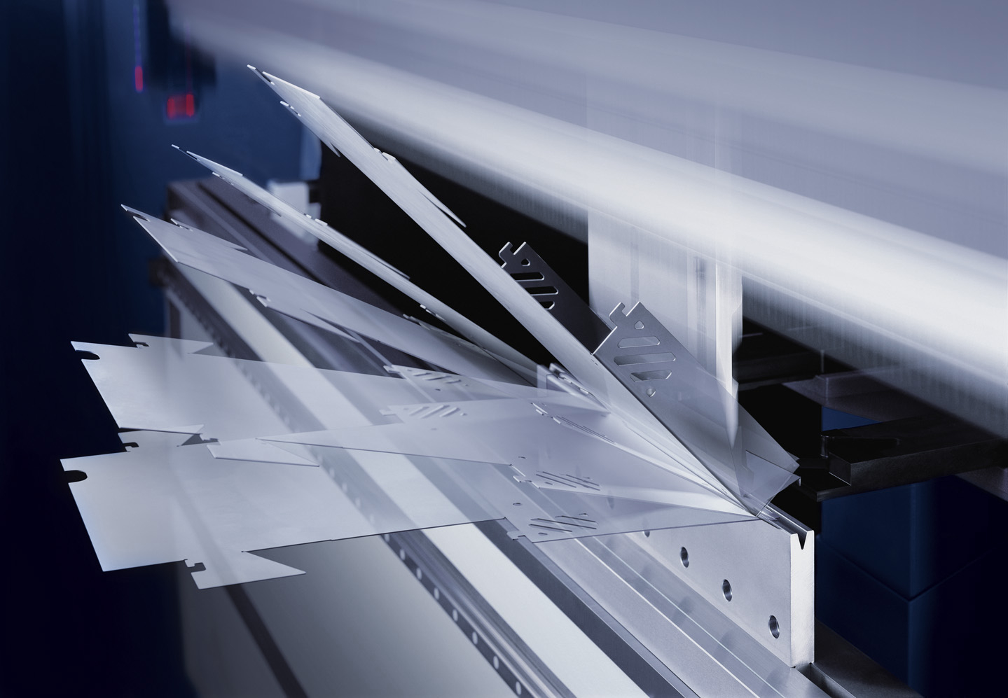
 Plastic deformation machining, the bending allows attaining elements with open section, essentially blanked in the length direction. It consists in subjecting the sheet metal to a bending stress with a load exceeding the limit of elasticity, to deform it permanently. The “V” bending is notoriously the most diffused technique for the sheet metal bending and depending on the punch stroke, is subdivided as follows.
Air bending: the punch does not reach the die bottom, so that the bending angle of the sheet metal is inferior to the characteristic angle of the “V” die.
- Advantages: it requires low bending force; it allows bending big thicknesses, varying the depth of the punch stroke it is possible to attain bends with different angles, without changing the die
- Disadvantages: the bending angle is influenced by the spring-back of the sheet metal; to attain the desired results, sheet metals with constant thickness and resistance often become necessary
Coining (at die bottom): the punch reaches the die bottom, so that the angle taken by the sheet metal is equal to the characteristic die angle.
- Advantages: the coining of the inner radius annuls the spring-back of the material, conferring high precision of the bending angle, it allows achieving smaller bending radii in comparison with the air bending technique
- Disadvantages: it requires high bending force (4-5 times the one needed by the air bending technique); it needs different tools for each angle and shape
It is instead the fruit of a process that develops in 2 phases the “hemming” (known also as edging, flattening), actually consisting in the sheet metal flattening, technique applied to obtain the manufactured good stiffness, protection of edges and to avoid sharp corners. Generally carried out with dedicated tools, it provides for a first pre-bending phase, exploiting the air bending technique, followed by a successive hemming phase (total or partial).
Pratical advices
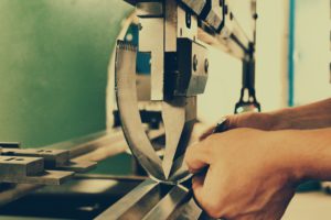
 Piece symmetricity control. When you have some doubts about that issue and the piece sizes allow it, you can avail yourself of a comfortable method to be certain you are doing the right thing: to overturn one piece on the other and assess the exact coincidence of templates.
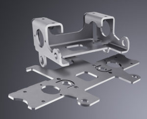
How to standardize small pieces in medium-high quantities cut from scraps. Especially when you are dealing with thicknesses of three millimetres or higher, the difference between one piece and the other is much felt. That diversity is due to the fact that we often prefer cutting pieces of small sizes inside bigger geometries or in the free spaces drawn from different sheet metals. This implies a great variability that is found in bending phase. A comfortable expedient can consist in dividing the pieces visually according to the sheet metal colour and the rolling sense. The operator will then proceed to the piece bending in batches. A subdivision according to the thickness can be useful and necessary, if it is high and shows a high variability.
Error management in progress. It can happen that the technical office has not considered precisely the material shrinkage and the operator has to solve the problem on machine board. If the part to be bent is “U”-shaped, errors are generally discharged on the flanges, to achieve an exact central measurement. The tendency is to be a bit shorter already with the first “flange”, attaining the unfinished piece that will still have the “L”-shape. Thanks to the first bend, it is possible to identify how much shrinkage has concerned the material. It is sufficient to measure the two sizes of the “L”, to calculate the theoretical and the real blank. If we deal, for instance, with a 3 mm-thickness to be “U”-bent, with 20 x 50 x 20 mm sizes, theoretically, with null shrinkage after the first bend, we attain an “L”, 20 x 64 mm. If we achieve for instance 19.7 x 63.0 mm size, it means that the material shrinkage was 0.8 mm: i.e. (17 + 61) – (16.7 + 60.5). At this stage, it is known that to obtain the central size of 50 mm, we will have to subtract 0.8 mm from the successive bend and to sum what is missing to the theoretical value of 64 mm, reducing it up to reaching 18.7 mm.
We thank for the collaboration Emiliano Corrieri, Accademia della Piegatura.
From the press brake to the robotic isle
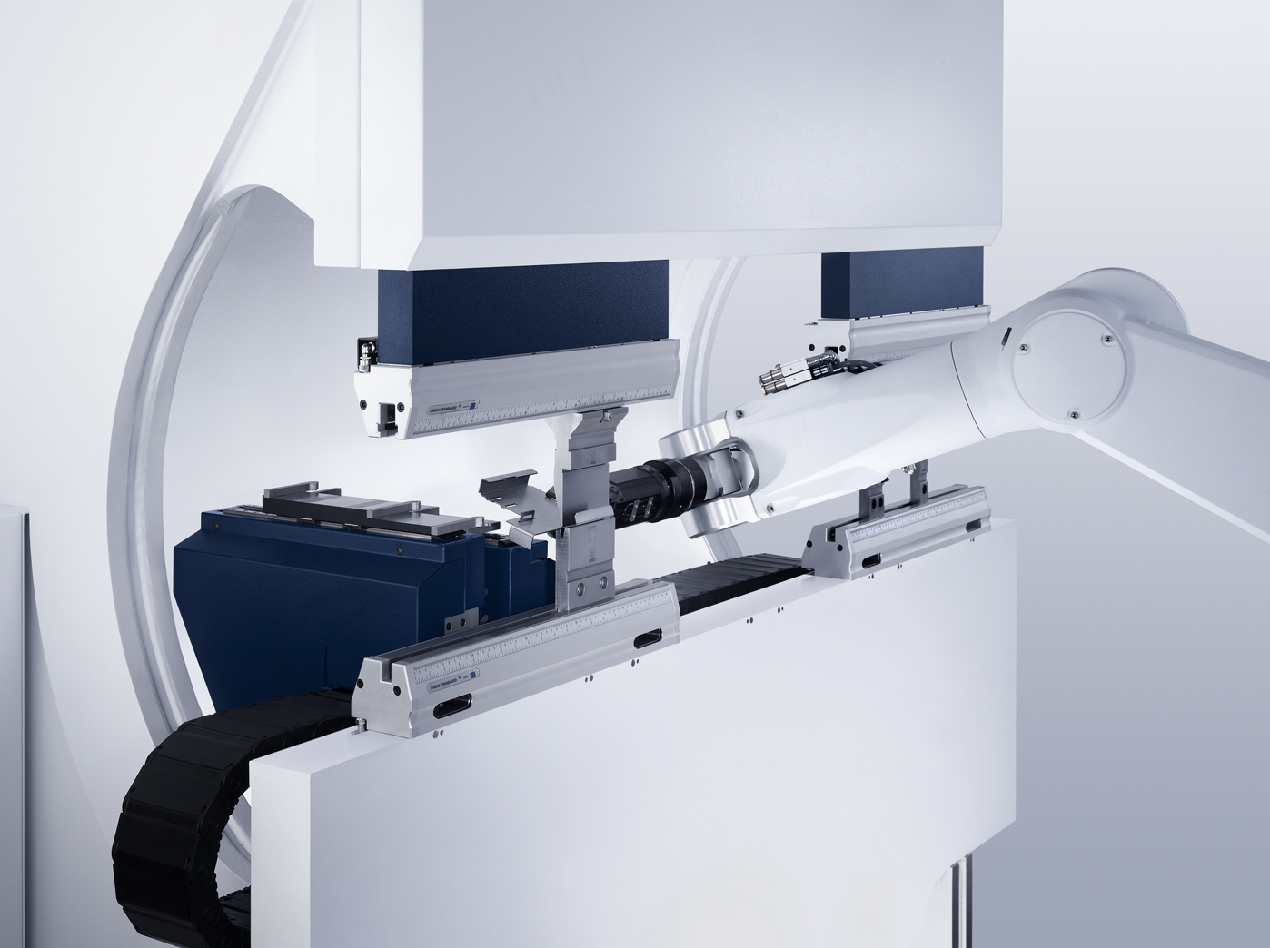 Over the last few years, machine manufacturers have evaluated the possibility of configuring robotic plants. What advantages? What opportunities? What elements worth considering for a winning choice? A lot undoubtedly depends on the type of company, on its sizes, on the prevailing typology of job orders and the supplied sectors. Once identified the typology of pieces to be processed, for the latter must be defined a likely range reporting the average number of bends and the feasible number for the manual execution in the time unit (one hour). All that considering the average times of tooling, programming, changeover, loading/unloading. Due focus also on the number of machine operators and their cost, on the possible shifts in the company and yearly working days, in addition to the cost of the press brake and the longed for revenue for each bend. These data must be compared with those attainable with a robotic plant (number of pieces that can be bent every hour etc.), taking into account the benefits in terms of unmanned operation and lower number of necessary operators. Production and economic data (with the possible addition of eventual more precise items concerning leasing, interest rates and so on), whose synthesis allows the evaluation of how the eventual investment can provide higher revenues, making use of a manual or of a robotic process.
Spotlights
The press brake is even more autonomous
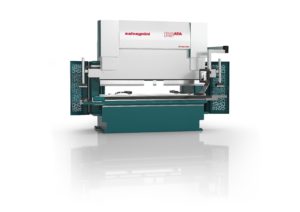 B3.ATA press brake by Salvagnini is essentially “Kitable” for its prearrangement to manage productions by kits thanks to the flexible tool adjustment system ATA. Acronym of Automatic Tool Adjuster, Ata allows the press brake to set and to suit the manufacturing part, adjusting automatically and in few seconds the upper tool length and the variable “V” slot width. The same system therefore recovers productive efficiency in case of bending of unitary batches or of parametric pieces. The prearrangement to be integrated and contextualized in a production system with “one piece flow” operation is then the fundamental structural characteristic for the new press brake. A machine that then proves to be “Adaptive”, too, since it manages to reach high levels of precision and repeatability thanks to the AMS (Angle Measurement System) and to the system called SCrowning. The first allows taking the bend to the correct angle, the second permits to maintain such angle for the entire bending length. AMS uses an optical laser system to achieve precise measurements also in presence of holes and cavities and can calculate the spring-back, irrespective of the material parameters introduced into the machine programme, and it can also calculate the angle actually obtained at the end of the bending. The SCrowning system regulates and compensates, in real time, the bending value of the press brake according to the real behaviour of the material under bending on the machine, making a comparison with what theoretically foreseen. Measuring the piece deformation in real time on the two direction lines and suiting the real bending conditions, the machine can understand whether we are bending well or badly for the entire bending length and react consequently.
The added value of hybrid press brakes
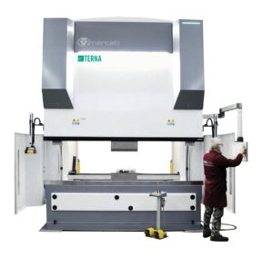 Vimercati press brakes of the e.Terna range are an innovative and extremely flexible product, oriented to “4.0 bending”. A system that can be installed on all models in production, with machines equipped with Siemens motors operated by an inverter, coupled with a Pressure Control system able to adapt pressures and speeds in real time. In this way, consumptions are optimized twice because on one hand the inverter, coupled with a high-efficiency pump, controls the main motor (and it activates it only when the machine starts running) and, on the other hand, the mentioned Pressure Control system grants the saving also during the machining phases, providing only the force needed for bending. The oil overheating notably decreases, too, improving the duration (the replacement is scheduled after about 20,000 hours of real operation). Even 50% of energy saving is instead calculated on critical bends in comparison with a conventional system. Also the CNC is equipped with new functions allowing the operator to monitor and to collect a series of useful data and parameters, including: the pressures visualized by digital manometers, energy consumptions, through a simple test that allows controlling the system efficiency in real time; a page dedicated to subcontractors, useful to assess in real time the production costs of the parts produced by the machine and to introduce them directly into the company’s managerial software. Moreover, the possibility of connecting the press brake in net favours the tele-service and facilitates the production: by means of an office programme, which can be installed on any PC of the company, it is possible to process the technical designs of the pieces to be implemented and to transfer then them directly on the machine. In this way, the operator can focus on the only bending operation, avoiding manufacturing delays caused by a long programming. The operator can also download and save the new parameters for the successive machining.
A hybrid with high performances and original design
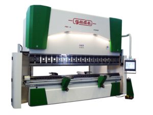 After the birth in 1991 of synchronized press brakes of the series “Praecisa” and in 2012 of the line “PSC Green Drive”, in 2016 at g.a.d.e. they conceived the series PSC-H Hybrid”. With the “PSC Green Drive”, g.a.d.e. had reached noteworthy levels of performance and energy saving but with the last product range it has gone much further: it has devised a hybrid press brake able to improve further both the energy saving and the performances but, especially, the range was expected to include also models with very high bending force (4,000/5,000 kN). Certified for years according to the UNI EN ISO 14001 regulation, with this new series of press brakes the company headquartered at Cologna (FE), has increasingly pursued the environment protection, through the energy consumption reduction, without diminishing, but on the contrary enhancing, the dynamic and precision features of the machine. The Iris system of LazerSafe, equipping as standard all press brakes of this range, assures instead higher operational speed: depending on the angular speed of the sheet metal during bending, the machine can bend with speed exceeding 12 mm/s. The same Iris system allows the speed change to “zero” mm from the sheet metal, bringing better dynamics and inferior idle times. Further distinguishing strong points concern then not only the drastic reduction of energy consumptions, up to 40%, thanks to the use of brushless motors for the servo-pump control but also the need of a minor quantity of hydraulic oil, since no heating is present due to the absence of servo-proportional directional valves. g.a.d.e. is an alive and beating company, despite the rumours diffused in the last months.
Technological Trends
Finite Element Modelling of combined plate process
Some researchers have presented the results of the Finite Element Modelling of a new combined process (Plate Rolling and Stamping). This process has been used to produce big-size bodies, for instance like the bottom of a vacuum container, the lower part of a ladle furnace and so on. Traditionally, such products (with upper wall thickness of 40 mm and maximum diameter width of 4000 mm) are produced in engineering companies that use stamping processes. Various implementation schemes of the present combined process have been investigated. The new combined process method for the production of rotating bodies (without using pressurized equipment) have been developed. The principle is the rolling of a pack of upper die, lower die and the flat thickness part between the two that is the core of the entire process. The FEM results of the combined rolling and stamping process with the aid of DEFORM 3D software have demonstrated that the main problems of the process are the fixity loss of the pack while rolling and the corresponding defects under the form of folds, increasing the consumption index and the manufacturing cost. The research and the 3D modelling of the two methods of the combined rolling process have been carried out. The 3D analysis highlighted that the deformation level is positioned close to the outer piece surface. A high value of deformation in the combined process emerges with parts having a thickness of 40 mm or higher and it can be critical in relation to discontinuity defects that appear in this zone. They have established that during the rolling method the highest stresses emerge especially on the pack, in particular on the areas of the upper and lower part of dies. Stress levels can reach 1000 MPa. Such high values of tensile stresses are mainly explained by the fact that the piece is hot and the tools (the upper and lower dies, the rolls) are cold, having the same environment temperature. They have established the process parameters (piece heating temperature, its thickness, the deformation speed, friction conditions) for the inverse deformation method. Modelling results have allowed optimizing the shapes of upper and lower dies and also the package implementation, taking into account the rolling and stamping process stability. The advantages and the defects of both combined process methods have been established. The inverse deformation method turned out to be preferable for the practical implementation, from the point of view of both the process stability and of the energy efficiency.
Source: Alexander Pesin, Ernst Drigunt, Denis Pustovoytov and Ilya Pesin, “Finite Element Modelling of Combined Process of Plate Rolling and Stamping”, The 12th International Conference on Numerical Methods in Industrial Forming Processes – NUMIFORM 2016, University of Technology of Troyes – France, 4-7


