 Monitoring of exposure to spindle vibrations during its operating is a powerful system that allows optimizing its maintenance plan. Machine tools maintenance is usually planned according to the “Mean Time to Failure” of the spindle. This method has no efficiency and effectiveness. It is not efficient because the spindle repair is carried out in advance, leading to unnecessary maintenance costs. It is not effective because, if the operations are particularly irregular, the spindle may be subjected to excessive efforts than those expected and it may prematurely break, leading to long and costly downtime.
An effective alternative is the “Condition Based Maintenance” (CBM) based on vibrations, bearing in mind that the operations carried out by the spindle are quite complex, with different speeds and loads acting on it that can generate different levels of vibration for each cutting process. Therefore it isn’t possible to use methods that are simply based on the level of vibration, as it is done for other types of rotating machines.
Method foundations
The MTBF (Medium Time Before Failure) of a machine tool is usually calculated/estimated considering the MTBF of its components, primarily bearings.
The life of a bearing can be calculated using the equations of ISO 281 international technical standard.
Machine tools usually operate at different speeds depending on the process. Considering the different operational speeds, without taking into account any changes in the dynamic load, the following formula is used:
RPM = q1RPM1 + q2RPM2 + … + qnRPMn
where qn are the percentages by which the spindle will work at particular speeds (RPM) during its lifetime.
Usually, for machine tools, there are different speeds for the various processes. The influence of speed can be introduced during design phase or the length of the spindle can be “recalculated” considering the programmed speed at operational level. Effects due to the machine’s different dynamic loads.
The same approach can be used for changing RPM, but it’s much harder to make an a priori estimate of dynamic loads..Loads acting on the spindle bearings are due to various causes: Static loads due to the weight of the spindle on bearings; Static loads due to pre-load; Dynamic loads transmitted directly by the engine or through the pulleys and gears; Dynamic loads due to imbalance of the rotor or the tool and Dynamic loads due to the cutting process.
The first three loads can be estimated; as a matter of fact ISO 281 and bearing producers provide general rules to calculate the equivalent dynamic load (P) acting on the bearing. The load due to the rotor or tool imbalance is not predictable but some general rules are considered on acceptable balance level regarding the bearing. The load due to the cutting process is almost entirely unpredictable.
Uncertainty about predicting dynamic loads is normally considered during the bearing’s design phase, introducing S0 safety factor, whose value depends on the operating conditions required for the bearing.
This safety factor depends on the type of bearing (ball or roller); for this purpose manufacturers recommend slightly different values:
Spindle bearings are normally chosen considering S0 = 3, on average, and with a life span from 20,000 to 30,000 hours. In addition, in workshops, as a precaution these values are reduced by 2.5 factor, bringing the “mean time to repair” of the bearing in the range between 8,000 and 12,000 hours. But is this approach safe? Could the time be reduced?
Improvement of current load knowledge through vibration monitoring
Dynamic loads on bearings and spindles are directly related to vibrations (velocity) through a simple ratio. However it is not possible to directly measure the dynamic loads in the workshop, due to the large dependence on vibration transducer positions, moving masses).
In any case, it can be said that, given a certain estimate of dynamic load P0, uncertainty can be expressed as a function of vibration. We can take V0 as a vibration level that does not produce specific effects; it is the acceptable level at which the spindle should undergo most of the time.
Which vibration is required for measurement?
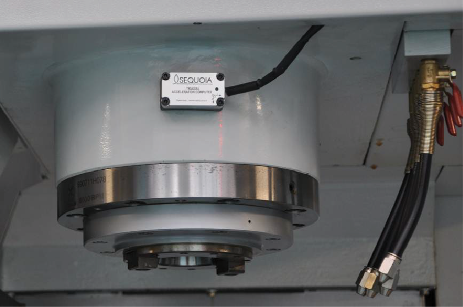
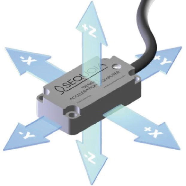
As indicated by ISO 10816-3, speed’s RMS is a good indicator of the severity of vibration operating on a machine. On a spindle it is advisable to take into account the dynamic loads acting in all directions. Therefore, as a single parameter, the best choice is vibration triaxial RMS module, to indirectly measure all vibrations linked to dynamic loads acting on the spindle.
A practical case
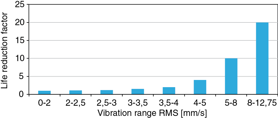
The proposed approach has been tested and evaluated on a set of 4 machine tools of the same type, with the same type of spindle, that operate in several fields: two machines for roughing, a machine for average milling and the last machine for finishing. For all these machines, despite their different operations, “Mean Time To Repair “(MTTR) has been set at 8,000 hours, based on estimated life span of 20,000 hours and a safety factor of 2.5. On each machine tool, SeTAC (Sequoia Tri-Axial Acceleration Computer) has been installed, with a dedicated firmware able to independently implement the proposed vibration approach and also: to measure the vibration tri-axial RMS module; to memorize how long the spindle is subjected to a certain level of vibrations; to calculate equivalent work hours based on the terms expressed by the equation and finally to estimate the remaining life span of the spindle. Subsequently the effect of the vibration level on the spindle’s life reduction can be calculated. As a reference, a safety factor S0 = 1 has been chosen, for V0 vibration level in the range 0-2 mm/s. As expected, a good repeatability of the two data sets has been spotted, confirming that no specific variations were introduced in the materials; the third and fourth machine have a bigger ratio of equivalent and real hours than the other two.
Optimized maintenance plan
 Spindle manufacturers recommend to check the conditions of the spindle and to care about its maintenance every 8,000 hours (based on the average MTBF). Obviously, this value is very conservative and for this reason maintenance is often not strictly necessary. In addition, even if planning maintenance every 8,000 hours, we found some unexpected breaks in the past, because we didn’t know the real loads and work that the spindle would be subjected to during the 8,000 hours. The implementation of the proposed monitoring strategy, as it has been implemented in SeTAC, avoids both unexpected breaks and unnecessary maintenance tasks.
To create a maintenance plan, a limit of 20,000 equivalent hours shall be deemed (i.e. 8,000 real hours multiplied by a factor of 2.5 that is typical of roughing machines that are more critical). This plan is automatically updated since it considers real vibrations to which spindles are subjected and allows the user to define the best time to schedule stoppages due to maintenance, thus improving efficiency (now, for example, it is more than 50% in relation to spindles’ finishing) and drastically reducing the risk of unexpected breakage.
Automatic adjustment of the maintenance plan is absolutely necessary, since the simple definition of a specific interval for each machine is not enough. As a matter of fact, the vibrations on a spindle can be influenced by various parameters: processed material; type and conditions of the tool compared to cutting parameters; wear and conditions of the machine.


