The French company Polysoude has recently developed a process with the goal to increase the productivity of TIG overlay welding operations to an economically interesting level.
Overlay welding, also referred to as cladding, is a well-established practice in the field of industrial production technology. The basic idea is to make workpieces of materials which are particular suitable for the manufacturing process of the current part, e.g. casting, forging etc. The “wetted” surfaces, i. e. the zones of the workpiece which will be exposed to an attacking medium, are accurately covered by a protective layer. The attacking media can be aggressive or hot gases like sour gas in the oil and gas production or exhaust gases from the combustion of fossil fuels; liquids with solved corrosive chemical agents like cooling water of the primary circuit in a nuclear reactor or with abrasive particles of rock as found in crude oil from an oil well; finally, solids like lumps of coal or ore and excavation waste as byproduct of mining operations. Workpieces can differ considerably in material, size, geometry etc. Examples of smaller parts with regular geometry are fittings for tubes and pipes, bigger rotationally symmetric components are power plant steam generator nozzles, the group of huge workpieces with complex geometries comprises e.g. vessels and vessel heads for nuclear reactors. Various processes can be used to carry out overlay welding. Manual welding is often applied because of its flexibility and simple equipment, shielded metal arc welding is selected if the specified tolerances are not too narrow and the quality requirements of the depot remain modest, high quality coatings can be obtained with manual gas tungsten arc welding. However, the results of manual welding always depend on the skills and personal form of each individual welder and conventional TIG welding is furthermore characterized by rather low melting rates. If the necessary equipment is available, the workpiece can be rotated in a favorable position and high heat input is not a concern, submerged arc welding can become the process of the choice. Modified gas metal arc welding stands for high productivity and satisfying results, for decades it has been the unrivaled favorite when it came to overlay welding operations. But, due to the growing demand for improved welding quality and tighter tolerances, in many cases the use of GMAW is not possible any longer. Instead, mechanized TIG welding is increasingly applied to complete delicate tasks, especially after recent process developments which led to higher melting rates and enhanced productivity.
Many companies use overlay welding during the manufacturing of components for their own product range. Their cladding equipment is usually geared to their applications, and after years of experience they have gained sufficient knowledge to get reliable results. Subcontractors for overlay welding are forced to adopt a completely different approach. These companies must react promptly on the requirements of the market, the set-up of their overlay welding equipment for quite different workpieces must be easy and rapid, proven experts in metallurgy and welding technique are needed to accompany the projects successfully, and last but not least is it up to skilled welders to ensure the expected quality of the coatings. An important subcontractor for overlay welding tasks is the British company Arc Energy Resources (AER). Concerning material, form and size of the workpieces the company covers a wide variety of possibilities.
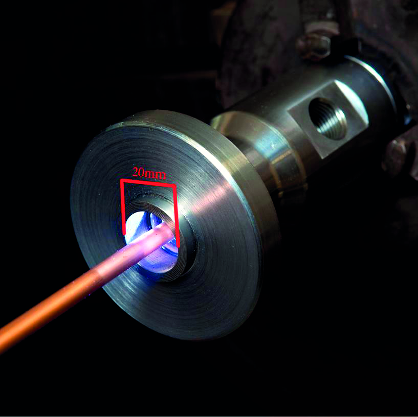
Among their smallest applications is the cladding of the inside of bores with a diameter of only 20 mm. Bigger components are generally limited to a weight of 15 t, the loading capacity of their hoisting devices. In 2016 the company faced a big challenge: two 30” valve bodies had to be clad. The scope of order included to cover all wetted surfaces with a corrosion resistant coating of two layers of 2.4856 (Inconel 625) by overlay welding, followed by corresponding machining operations, pressure tests and non-destructive testing. The first rough casting arrived with a total mass of 27 t, which far exceeded the lifting capacity of the installed indoor crane of the workshop.
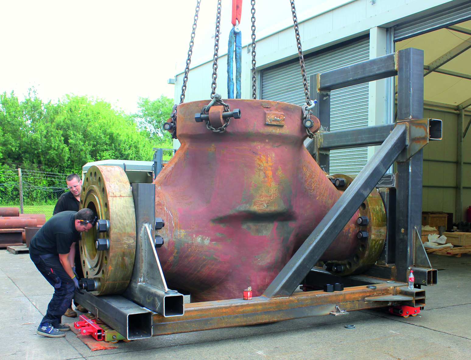
A hired mobile crane with a sufficient capacity could not be operated inside the existing building, so a new hall of lightweight construction had to be erected nearby. A further complication arose from the extremely short delivery time which had been imposed by the customer. The specified quality of the coatings could only be guaranteed if TIG overlay welding would be applied, but the available welding installations were designed for the conventional TIG process, which is characterized by low melting rates and poor productivity. Hence, the equipment they already had was not suitable to finish the work on time.
State-of-the-art TIG overlay welding
The French company Polysoude, a renowned manufacturer of state-of-the-art equipment for mechanized and automated welding, has recently developed a process with the goal to increase the productivity of TIG overlay welding operations to an economically interesting level. The new TIGer technology (Tungsten Inert Gas electrical reinforcement) is based on an especially designed bi-cathodic welding torch with two tungsten electrodes in tandem configuration. These electrodes are supplied separately with welding current from two independent power sources, but due to their particular layout the resulting single arc provides distinct advantages for overlay welding purposes. Compared to the conventional TIG process at the same welding current intensity the pressure which prevails in the arc is significantly lower. Thus, elevated welding currents and faster welding speeds can be reached, whereas the welding process remains stable and less penetration occurs. At the same time, the specific heat input of the weld is considerably reduced. A further improvement of productivity comes from the hot wire technique. The energy to melt down the filler material must be generated by the arc, so the feeding speed of filler wire is limited. In the hot wire technique however a particular hot wire current is supplied by a dedicated power source, so the filler wire arrives pre-heated at the molten pool of the weld and absorbs less energy. As the calculations showed, with the new technique it would be possible for AER to meet the delivery date and to finish the cladding of the 27 t valves on time.
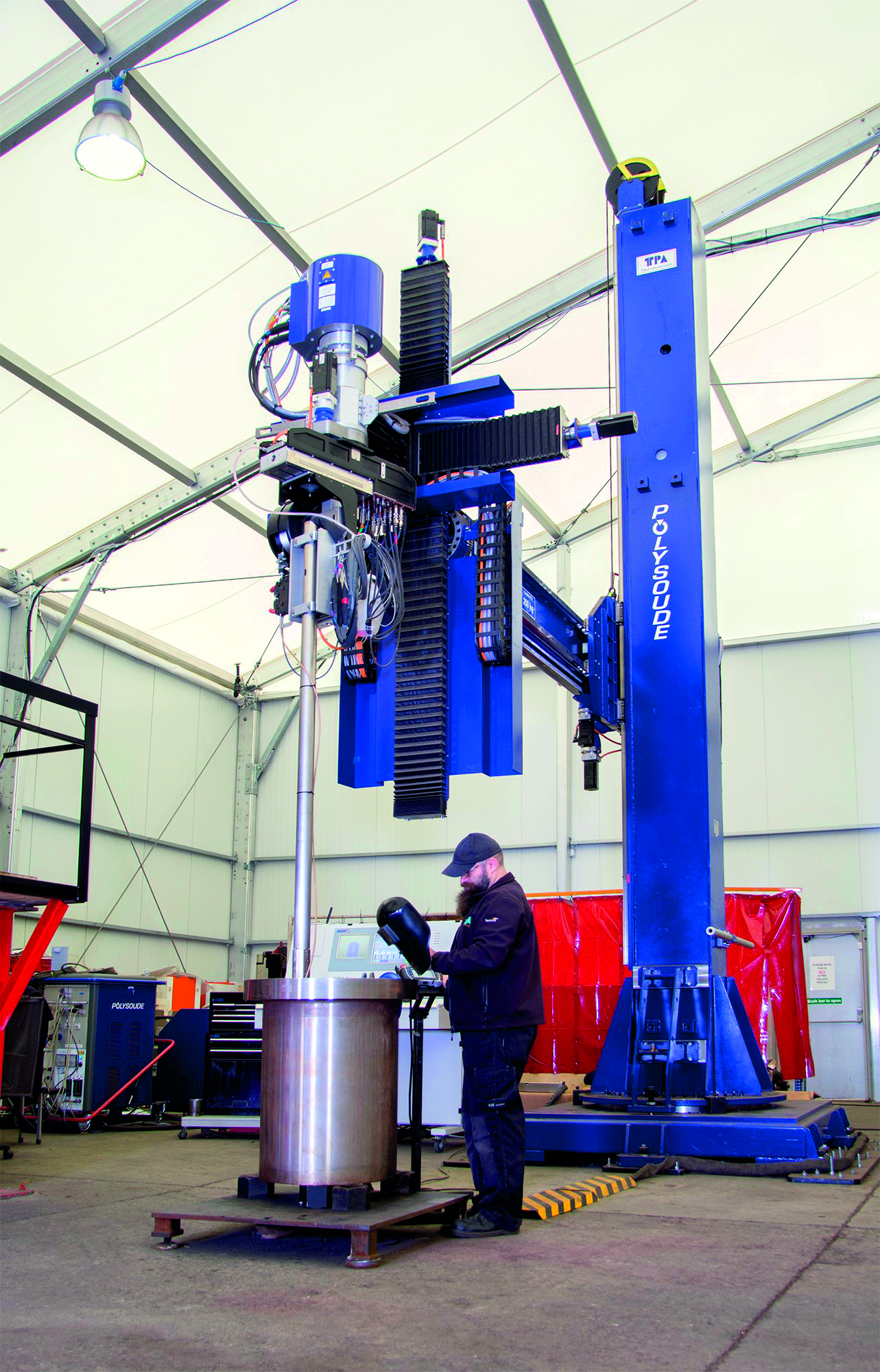
Based on an elaborate case study about the surfaces to be clad, their accessibility inside the valve bodies and the necessary workpiece position Polysoude proposed an overlay welding installation composed of:
-a column and boom device for the vertical and horizontal positioning of the equipment with additional cross-slides for precise movements of the welding tools
-a welding set of conventional and TIGer torches, mounted on corresponding welding lances two articulated TIG cladding lances with different lengths
-two articulated TIGer cladding lances with different lengths
-an SPX device (endless rotating collector with quick release connections to held the welding lance)
-the necessary ancillary equipment like power sources, cooling units, control cabinet etc.
The proposal was generally accepted by AER, but as subcontracting company they also voted to preserve all possibilities and options for the later use of their future equipment. So it was agreed that the installation should come with a CNC control.
Development and implementation of a suitable CNC control for the cladding installation
CNC (Computer Numerical Control) is a versatile technique which has been mainly created for the automation of machine tools. Up to that time, Polysoude had delivered all welding installations with their proper control system, which, as result of many years of experience and continuous development, works safe and reliable. However, the flexible CNC command software had to be adapted to the specific needs of overlay welding equipment, an excellent opportunity to create a modern, suiting human-machine-interface. A close cooperation between Polysoude and AER should ensure that all necessary functions were arranged to support the operator in a user-friendly manner. The entire data for a welding sequence has to be programmed in advance. Depending on different cladding choices and according to the desired type of application different screens become accessible:
-Tool path screen (input of the geometric characteristics – path definition, visualization, …)
-Welding parameters screen (input / correction of the parameters on a pre-established base)
-Torch definition screen (choice of tools to facilitate the path tracking)
-Production screen (different modes, cycle, simulation, visualization / position, number of turns, recovery)
-Variables screen display – variables consultation (trajectories, speeds, parameters).
Additionally to the selection of the type of cladding, the application, the tools, the welding parameters etc. it is possible to store characteristic data about the workpiece: order no., designation, material, dimensions, etc. This data is useful if, after some time, the same order shall be executed again or a similar workpiece shall be clad.
Preparation of the final overlay welding operations
The start of the overlay welding operations was preceded by wide-ranging preparations. 7 different welding procedures had to be qualified, including 4G and 2G TIGer cladding with high and higher deposition rates. As AER had virtually no experience with the trustworthiness of the TIGer technology a set of parameters for a high deposition rate and a second one for an even higher deposition rate were approved, in case of problems with the faster procedure the high deposition rate parameters could have been applied. As the final column and boom equipment was not available at that time, to allow the approval on time, Polysoude installed a preliminary unit with the TIGer technology on the AER premises. It was also the task of AER to design and manufacture a fixture to hold the 27t valve bodies during the cladding operations in 5 specified positions.
Carrying out the final overlay welding operations
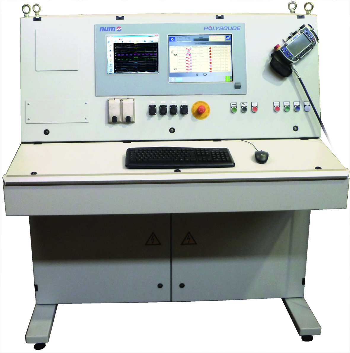
With the column and boom equipment mounted on site, the fine-tuning of the installation could be carried out. At the application centre of Polysoude in Nantes, the welding staff of AER had already got a detailed training on the operation of the machines. The commands are given from a control cabinet, a touch screen at the left side grants access to the programs with the welding sequences, whereas the welding parameters are displayed in real-time on the left screen. The commands can also be transmitted by a remote control pendant “nPad” which serves as mobile unit. During the simulation of the cladding operations without arc the welding personnel had the opportunity to refresh and practise the acquired skills under realistic conditions. It turned out that the CNC control reacted too sensible at the surface of the rough casting; the tolerances are finally quite different from the admitted tolerances of a workpiece in a machine tool. Anyhow, the problem could be solved by some modifications of the software. A suggestion for improvement concerned the “remaining” surfaces on the workpiece, which could not be covered by using the proposed applications from the system library. The suggestion had been considered to be very useful, so an additional subroutine was implemented to the program which calculated a particular trajectory from reference points, which had to be set at the edges of the remaining surfaces.
The careful planning and comprehensive preparation of the project as well as the narrow collaboration between equipment manufacturer and customer had ensured the success of the project: the cladding operations on the two workpieces could be finished some time before the scheduled date. An unexpected gain of productivity had been achieved due to the extremely low specific energy input of the TIGer cladding process of only 0.54kJ/mm. Despite the low heat input the test coupons had shown a maximum hardness HV 10 of only 250, i.e. no dangerous hardening of the depot or HAZ had to be feared. However, the temperature of the valve body rose only moderately during the cladding, so no interruptions had become necessary to cool down the workpiece. Subsequent use of the equipment Actually, the column and boom equipment is used for a different cladding application: the inside of 22 cylinders, which will become the sleeves for the ends of flexible hose connectors, has to be coated. The process time in case of cladding with the conventional TIG equipment would have been 79h per component, with the TIGer technology at a deposition rate of 3.3kg/h this time is decreased to only 19h.
Conclusion
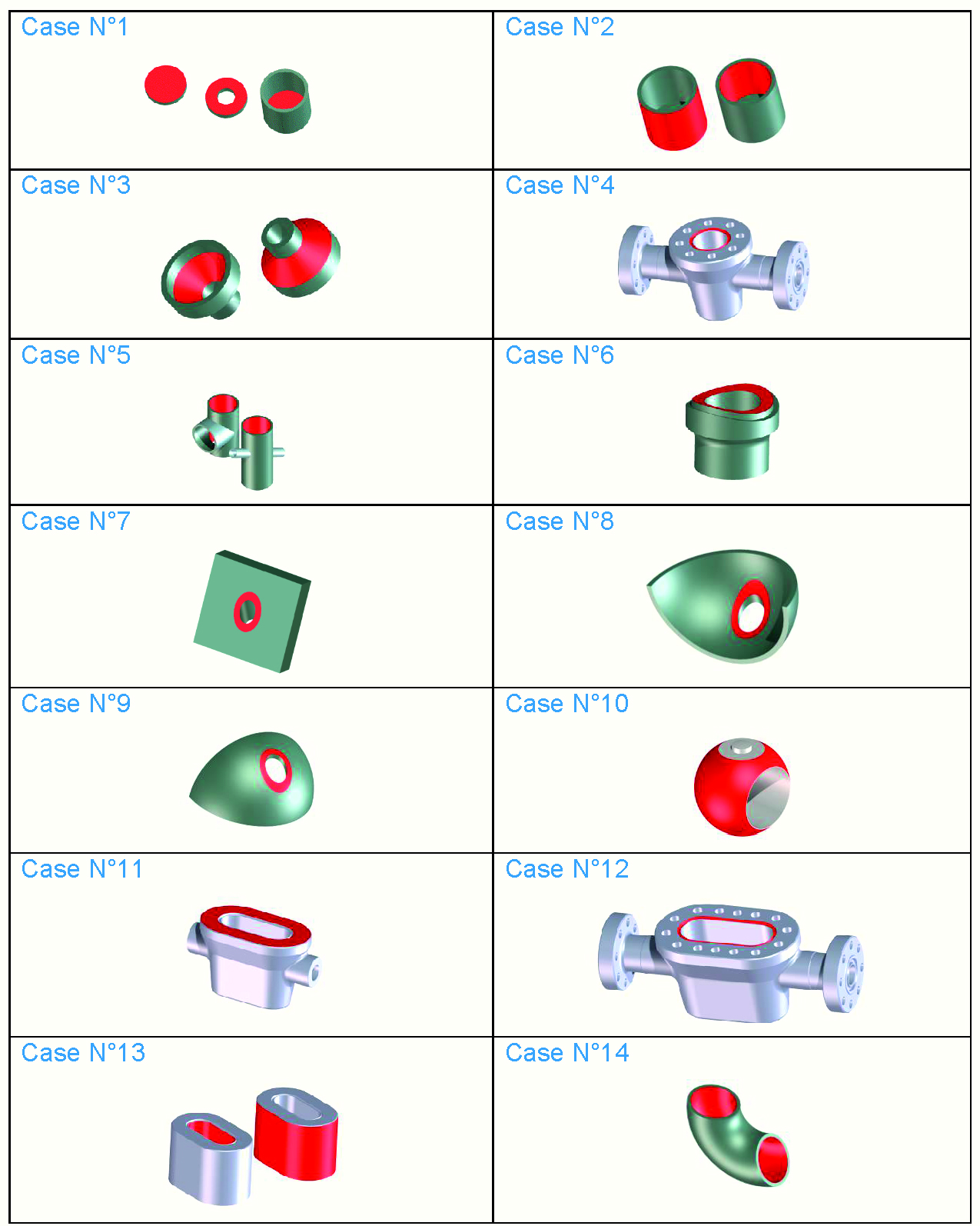
Together with the recently developed TIGer technology, state-of-the-art equipment allows to carry out weld overlay operations on virtually any workpiece geometry. A considerable reduction of process time can be achieved without any loss of coating quality. The versatility of the TIGer technology and the easy-to-use graphical user interface allows using the installations in a very flexible manner, an interesting advantage especially for subcontracting companies.


