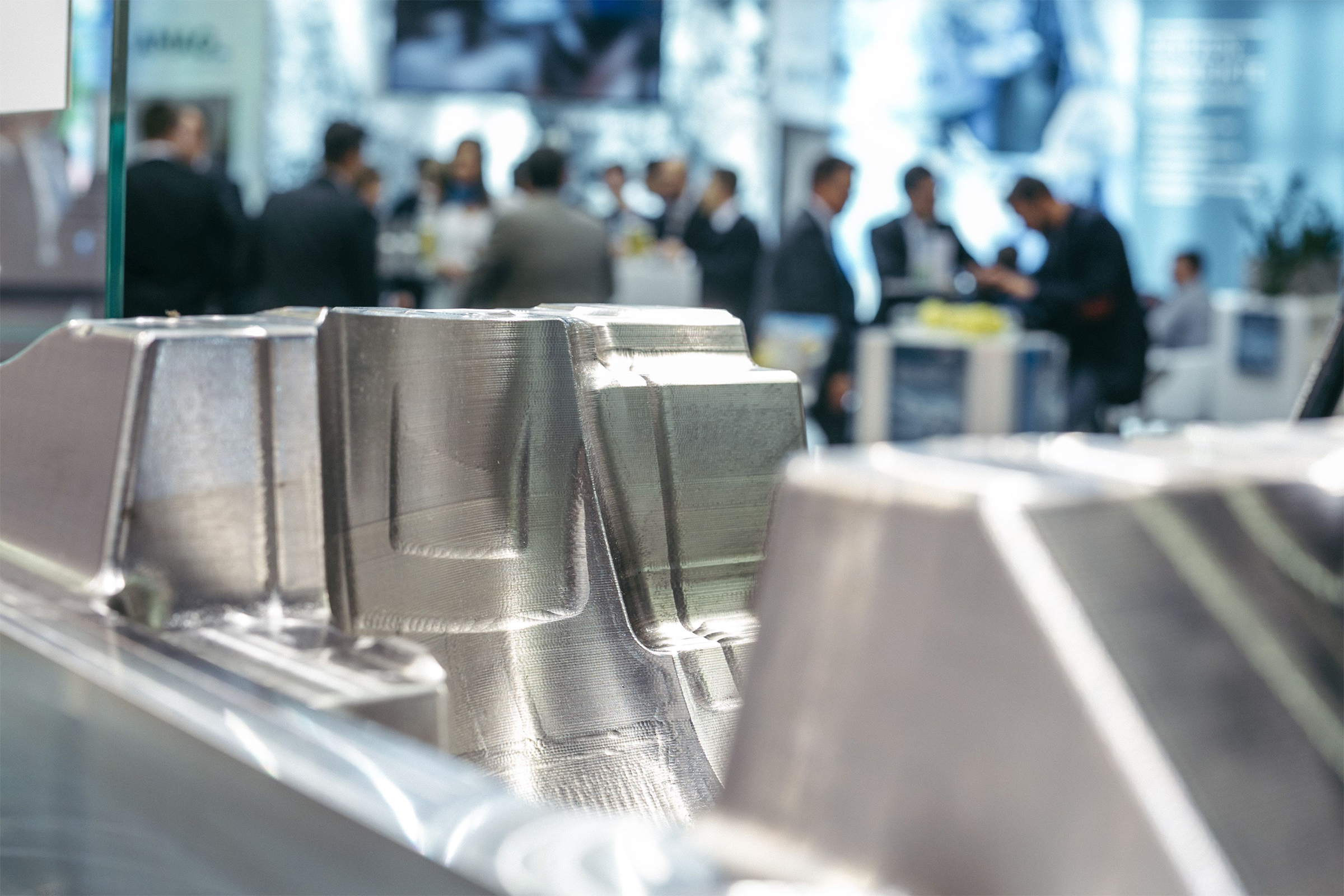
A central issue regarding the die casting process is the mould. It determines the contours of a die cast part and affects its properties. Mouldmaking still has a huge development potential, particularly in view of using additive manufacturing processes.
 Die casting is a forming process for the mass production of parts made from aluminium, zinc, magnesium, copper, lead, tin and their alloys. The casting process takes place in die casting machines which are divided in hot chamber and cold chamber die casting machines. The main difference is that in hot chamber casting machines the container with the molten metal is located inside the machine, while in the other case the container is placed outside the machine. In both types of machines, the molten metal is pressed from a casting chamber through one or more casting channels into the cavity of a permanent steel mould where it takes the shape which is determined by the die and solidifies. These die casting moulds consist of two halves in order that the cast part can be removed from the mould. The feed side mould half is mounted on a fixed plate on the rigid side of the die casting machine, while the ejector side mould half is mounted on a movable plate placed on the other side. Before closing, the halves are sprayed with a release agent so that later the cast part can be easily released from the mould and the plates do not overheat. Depending on the size of cast parts, up to 300 casting cycles per hour can be carried out.
Extreme loads
When the mould is closed, the melt is pressed into the mould under a pressure of up to 1,200 bar, achieving maximum mould filling speeds of 150 m/s (540 km/h) [1]. High closing and clamping forces are required to press the mould halves against each other and keep the moulds closed: up to 8,000 kN (800 t) in hot chamber die casting machines and up to 45,000 kN (4,500 t) in cold chamber die casting machines. By using such high forces, large-sized cast parts can be manufactured. Concerning material and design, the moulds that are used for this purpose must be designed in such a way that they can permanently withstand the loads related to the large melt quantities. When the metal has solidified, the mould halves open and the cast part is ejected by bolts or removed by a robot and conveyed for further processing.
High performance steels
A central issue regarding the die casting process is the mould. It determines the contours that have to be transferred to the cast part and should also enable the cast part to solidify as quickly as possible. In this way, the formation of a fine-grained microstructure is promoted, which is beneficial to the casting quality. In order to achieve optimal cooling, the moulds are cooled in certain parts. Another effect is that the production time is shortened, which provides economic advantages. The design of die casting tools is described in the standard DIN 16760-1 [2]. The tools used in the die casting process are inevitably exposed to high thermal and mechanical loads and must be able to withstand them permanently. For example, moulds for zinc die casting reach service lives of 500,000 to 2 million cycles. In order to achieve such performances, the die casting tools, which besides the above mentioned moulds include mould inserts, cores, slides and ejectors, are made of high-strength hot-work steels such as X40CrMoV5-1 (1.2344) or special materials, for example hard metals. Properties that play a very important role in these tools are high wear resistance, high ductility, high heat resistance, high hot tearing and hot wear resistance and good thermal conductivity. When choosing the materials, their technological properties, the design of the tools, their heat treatment and last but not least the complex interactions between the tools and the metal to be cast must be considered. For this purpose, the manufacturers and suppliers of the appropriate steels offer informative brochures and consulting services [3].
CAD/CAM systems
In the past, tools for the die casting technology were manufactured on the basis of drawings, today designers work with 3D CAD data and use state-of-the-art IT technologies. In the design of casting moulds, both the casting process – and thus the melt flow and the cooling – and the geometry and the dimensions of the die cast parts to be manufactured must be considered. The cast parts should be characterized by a uniform, fine-grained microstructure, high dimensional accuracy and dimensional stability and a high surface quality. Computer-aided simulation calculations help to make the tools optimally adapted to the die cast parts. Toolmakers and mouldmakers use CAM systems for manufacturing. CNC controlled milling machines as well as die sinking and cut erosion machines are used to incorporate the forming contours into the moulding material with high precision. The manufacture of the moulds is very complex and therefore expensive. The tooling cost is in the order of up to 20 % of the total cost of an aluminium die cast part [3]. For the production of components in large series, however, this is more cost-effective from a certain lot size onwards than manufacturing the parts in other ways, for example by machining processes. In addition, the manufacturing time for each part is shorter. A standardized, time-saving procedure for the design of die casting tools has been developed at the Institute of Machine Design at the University of Magdeburg, Germany [4].
Still a lot of potential
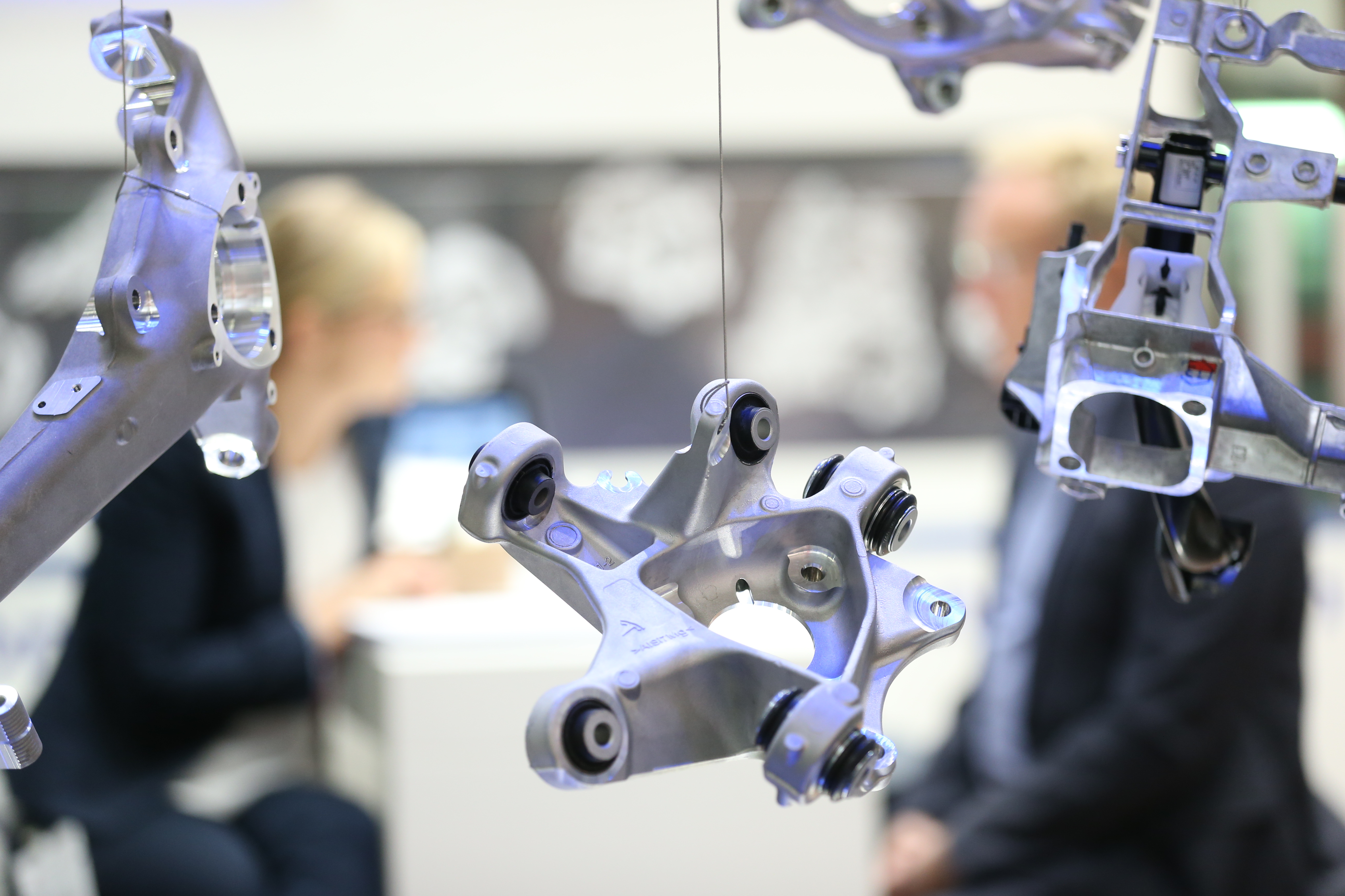
The design diversity of die cast parts and the demands placed upon them are continually growing. Therefore, the demands on the properties of the tool steels used for die casting and the constructive design of the tools and moulds manufactured from these steels are increasing too. These steels, the software programs foreseen for design and simulation and the capability of the machining systems are subject to constant development. The topics “digitization” (Industry 4.0) and “3D printing” are gaining increasing importance. Trade fairs are responding to this trend. The EUROGUSS pays special attention to this topic with the special show „Additive Manufacturing“. By using digital technologies, processes can be controlled more efficiently and the optimization potential can be better recognized. With 3D printing processes (“additive manufacturing”), it is possible to make parts which cannot be manufactured by conventional processes, for example inserts for die casting moulds with a complex shape and integrated cooling channels which are close-to-contour and curved. According to Dr.-Ing. Ioannis Ioannidis, President and CEO of the die casting machine manufacturer Oskar Frech and Chairman of the Foundry Machinery Association and Member of the Board of the Additive Manufacturing Association in the German Machinery and Plant Manufacturers Association VDMA, believes that in this area is still a lot of potential for mould making: “The complete heat management in the mould can be affected in such a way that, for example, the mould is better protected against wear and the quality of the part to be cast can be affected.”[5]


