The formation of defects such as a cold-shut or a critical surface imperfection, up to the missing filling, can derive from a series of process contributing factors that, if identified, allow determining the corrective interventions. we are illustrating how the virtual simulation and the mathematical analysis can provide a valid support to face that.
 In die casting, it is not simple to identify the causes that generate a micro or a macro defect. The formation of a cold-shut, a missing filling or a critical surface imperfection can often derive from a series of process contributing factors that, if identified, allow determining the most opportune corrective interventions. The work of the engineer, who avails himself of a virtual simulation tool, includes the knowledge of the process, its “numerical” expression and the ability of interpreting the results provided by the predictive instrument, identifying what will really happen in production, foreseeing the onset of defects and finally motivating their causes. In sampling and production phase, the simulation becomes an investigation instrument to identify the most opportune parameters to minimize the defects actually detected. The virtual survey instrument (that’s to say the simulator) must in its turn grant the reliability of the results that it supplies, mirroring what happens in the productive reality.
The numerical computation applied to foundry
From a theoretical point of view, the phenomena that are at the base of foundry processes are certainly well-known:
• the filling of a die (or a mould) by means of an alloy at the liquid state follows the fluid dynamics laws (equations of Navier-Stokes); they are, more precisely, equations of continuity, conservation of momentum and energy, which are expected to satisfy the balances of mass, momentum and enthalpy. They can be written in the following general form: 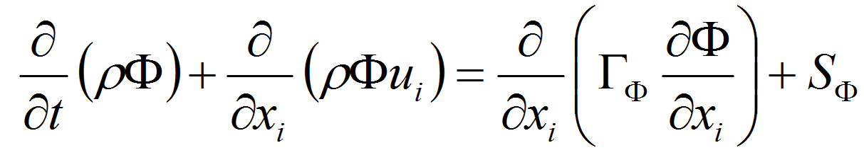
where the terms respectively represent the non-stationary state, the convection, the diffusion and an opportune source. The dependent variable can indicate different quantities, like the fraction of mass, the enthalpy, the temperature, a speed component, the kinetic energy of turbulence. Depending on the dependent variable chosen, a different meaning must be attributed to the diffusion coefficient and to the term related to the source. To make an example, if we particularize the equation (1) to represent the conservation of the momentum, the dependent variable becomes a component of the speed, the diffusion coefficient becomes the thermal conductivity and the source is given by the external acting forces.
• the solidification and the successive cooling of the alloy occur according to what provided for by the heat equation by Fourier; for the thermal qi flow, of a material characterized by K thermal conductivity and, referred to a field of T temperatures, the equation is written: 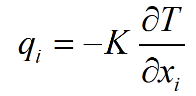
• the eventual phase transformations to which the solidified alloy can be subjected are described in thermodynamic and kinetic terms by the laws of physical metallurgy.
The Reynolds equations averaged Navier-Stokes (RANS)
In the standard formulation the Navier-Stokes equations concern the laminar flow but they can be applied to the turbulent one if instantaneous values are attributed to all variables. It proves therefore convenient to break out the instantaneous value of (which in this case represents the three components of the speed vector and the pressure) into a mean component and a fluctuating component. After that resolution, an averaging operation is applied to the vector equation of the momentum, thus obtaining the Reynolds equations averaged Navier-Stokes (or RANS): those equations confine the contribution of the fluctuating terms (which make the simulations of complex problems not practically implementable owing to the current limited computation resources) inside the Reynolds stress tensor. Such tensor introduces six additional unknowns (symmetric tensor) to the system of differential equations given by the product of the components of the fluctuating speed vector. The modelling of that tensor, and consequently the closing of the system of PDEs (System of balance equations) is entrusted to the model of turbulence closing chosen. The new field variables of the turbulence model are the turbulent kinetic energy together with the dissipation coefficient of the turbulent kinetic energy. The whole of equations of that model is written for mean magnitudes and using dimensionless parameters. Besides, it is used a computation algorithm able to simulate the pseudo-plastic behaviour of a non-Newtonian fluid. It is also worth considering that, introducing the coefficient of surface tension of a specific fluid, it is possible to examine the effect of the latter depending on the investigated fluid and the present boundary conditions (such as the temperature, the speed, the pressures and the materials in contact). The reference equations (1) and (2) are treated in the approaches of numerical type reducing them in different ways to systems of algebraic equations. The paths followed are necessarily different in relation to the method chosen, but also, inside each method, in relation to the numerical approximations introduced as well as to the explicit variables. The numerical approaches, followed by the majority of commercial software that treat the problem of the process simulation in foundry exhaustively, include both the cavity filling phase and the solidification phase, and they are mainly three:
• the method of finite differences (FD): it is the method used to solve numerically the differential equations, prevailingly ordinary even if they are often used as scheme of advancement in time for problems to partial derivatives;
• the method of control volumes (CV): it is a useful method in the integration of differential equations to partial derivatives. Those equations must be integrated into a volume on which borders are imposed the boundary conditions;
• the method of finite elements (FE): it is the suitable numerical method for searching approximate solutions of problems described by differential equations to partial derivatives, reducing the latter to a system of algebraic equations.
The best answer to such demands for the codes of fluid-dynamic computation is provided by the method control volumes that allows describing the flow, in this case of the alloy, with good precision, the higher when the greater is the number of volumes that discretize the geometry that is the study issue. Moreover, the method is suitable for a simpler and more immediate formulation of the discretization itself, making the meshing system more streamlined and simpler in the setting by the user.
The reliability of virtual analyses
In the use of whatever computation code, the validity of final results is direct consequence of the correctness of the input information provided. In principle, we can therefore state that the main phases of a foundry process can be described by mathematical formulations, more or less complex, above described. Therefore, the reliability of the physical-mathematical analysis significantly depends, at this stage, on the correctness with which the boundary conditions are defined and on the knowledge of the properties of the examined materials.
[su_slider source=”media: 626,627,628,629,630″]
By means of the boundary conditions we can take into account some essential operational parameters of the process, such as:
• the geometrical configuration of the system that we want to simulate (casting, dies, thermoregulation circuits);
• the parameters that characterize the process: that’s to say the casting temperature, the flows of melted metal, the various operational phases that mark the cycle time (opening of casting parts, the lubrication instants, the closing of the casting parts, the injection of the alloy into the die, the solidification phase).
The precision of such information is as essential as the numerical calculation methods applied and previously mentioned. Therefore, the higher are the pertinence and the precision of the information input into the calculation code the higher will be the precision of the virtual result.
Further fundamental input in the virtual calculation consists in the numerical characterization of the thermo-physical properties of materials (that’s to say alloys and steels for casting parts). They must in fact be known (or at least reasonably estimated):
• for the alloy: the temperature of liquidus and of solidus and, depending on the temperature, the viscosity, the density, the conductivity, the thermal diffusivities and the surface tension;
• for the die (and for the cores): the thermal properties and the characteristics of possible cooling systems;
• the thermal exchange coefficients that regulate the passage of the heat flow through different bodies in contact according to the present contact conditions (such as surface roughness, the contact pressure).
All these information can be experimentally deduced with some specific lab tests and the use of software enabling their identification. Obviously, the competence and the specific knowledge in the metallurgy sector complete the picture of the specific characterization of a material.
Short examples of virtual analyses compared with the real production
The identification of the presence of air incorporations, which appear under the form of more or less big bubbles inside or instead on the surface of the piece. They can in fact be identified through the use of the Air pressure criterion. Thanks to the activation of the virtual X-ray option, it is possible to identify the zones affected by the problem and the related criticality level (see the Figure number 1). The analysis is then extended, evaluating the filling dynamics, in order to be able to identify the causes of the missing air breathing in the direction of the apposite wells. The identification of flow fronts that tend to sub-cool during the filling phase allows foreseeing the problems connected with the formation of cold-shuts or even the lacking filling (as per Figure 2), exploiting the analysis of the filling dynamics according to the distribution of the alloy temperature. The analysis of the solidification phase allows identifying its evolution by visualizing the insulation of the massive zones that give birth to the formation of shrinkage porosity (in Figure 3). The application of the virtual X-ray option, which allows making the already solidified parts transparent while highlighting the critical zones, provides the user with a valid support, permitting to identify the present defects more easily. The virtual analysis allows focusing the attention also on the criticalities concerning the cast parts. An analysis carried out at thermal regime, that’s to say considering more productive cycles, provides a valid contribution to identify, just to make a further example, what are the die zones subjected to deterioration owing to the thermal shock to which they are subjected, then predicting the fatigue life of the die itself (the reference is in Figure 4).
The results of a die casting simulation
The results that we can obtain from a virtual analysis system can be subdivided into the following categories:
• the representations of the fluid-dynamic field of the system, that’s to say of the distributions of mass and temperature during the cavity filling;
• the representations of the thermal field of the casting, that’s to say the distributions of temperature during the solidification and cooling phases;
• the reprocessing of the information deriving from the fluid-dynamic and thermal field, able to allow an assessment of the possible defects of the casting;
• the visualization of the temperature distributions in the die in the course of all the phases of the productive process;
• the visualization of the evolution of residual stresses and deformations of the casting as well as of the stresses on the casting parts.
The new frontier of simulation: the multi-target optimization
The systems of Multi-Target Automatic Optimization coordinate the die-casting simulations with the aim of identifying the optimal configuration able to minimize or to eliminate the defects, at the same time enhancing the overall quality of each product at best. The comparison among a high number of potentially applicable solutions is made possible by the introduction of variables that can manage the geometrical shape and/or the process parameters inside determinate conditions imposed by the engineer. Moreover, the engineer himself is called to define the targets to be pursued, in order to identify the optimal configuration. All these targets, which are actually manifold and contrasting, can concern both the aspects regarding the casting quality and alternatively the life of casting parts, thus leading to the definition of the optimal configuration for the productive process (see Figure 5). The increment of the number of the variables used and of the requested targets determines the complexity of the problem, with the unavoidable difficulty, for the engineer, of identifying the best possible configuration.
For further information:
Giampietro Scarpa – EnginSoft


